Brake disk

a technology of brake discs and cylinders, applied in the direction of brake discs, braking elements, brake types, etc., can solve the problems of large difference in mass between the friction surface and the extension, the connection of components can bend, and the friction surface can be detached from its seat, so as to improve the entry of air, improve the effect of airflow and reduce the tendency to crack formation of these components

Inactive Publication Date: 2013-08-20
ROBERT BOSCH GMBH
View PDF23 Cites 6 Cited by
  • Summary
  • Abstract
  • Description
  • Claims
  • Application Information

AI Technical Summary

Benefits of technology

[0004]An example brake disk according to the present invention may have the advantage that the existing conditions of installation of the brake disk do not have to be modified, but the flow of air is improved. Due to the fact that the extensions for guiding the connecting parts are integrally formed on the cross-bearers of the friction surfaces, an air space is created between the extension and the friction surfaces that improves the entry of air into the cooling ducts. In order to transmit the braking moment, the extension for guiding the connecting elements can be supported in a simple manner on the cross-bearers of the friction surfaces. For the supporting itself, no additional components are required, because the supporting takes place on the already-existing cross-bearers, so that the cross-bearers take on an additional function. In addition, through this measure the ratio of 3:1 between the wall thickness of the friction surface and the connecting elements can be ideally maintained. At this thickness ratio, not only is the temperature gradient between the friction surfaces and the extension modified, but cooling air also flows around the extension itself. The tendency to crack formation of these components is thereby reduced. The ventilation now taking place over almost the entire circumference of the extension for guiding the connecting elements results in a low heating of the extension. This has the result that only slight differences occur in the thermal expansion for the connecting elements, which are normally made of steel, and the extension, standardly made of cast iron. As a result, the movability of the pins in the bore of the extension is ensured in all temperature ranges during operation. It is possible to manufacture the extension with various outer geometries or outer contours. Given the use of a round or cylindrical outer contour, it is possible to process the outer contour and the bore for the connecting elements simultaneously and easily.

Problems solved by technology

However, given larger torques there is the danger that, due to the free length of the connecting elements, i.e., due to the distance between the bearer part and the friction ring, the connecting elements can bend, and in the extreme case can become detached from their seat.
This results in a large difference in mass between the friction surfaces and that of the extension.
During operation, i.e., during braking, this causes a high temperature gradient between the extension and the friction surfaces.
This causes high tension gradients that in the extreme case can cause crack formation in the friction surfaces.
In addition, due to the size of the extensions the entry of air into the cooling ducts of the brake disk, situated between the friction surfaces, is impeded.
The ventilation now taking place over almost the entire circumference of the extension for guiding the connecting elements results in a low heating of the extension.

Method used


Image

  • Brake disk
  • Brake disk
  • Brake disk

Examples


Embodiment Construction

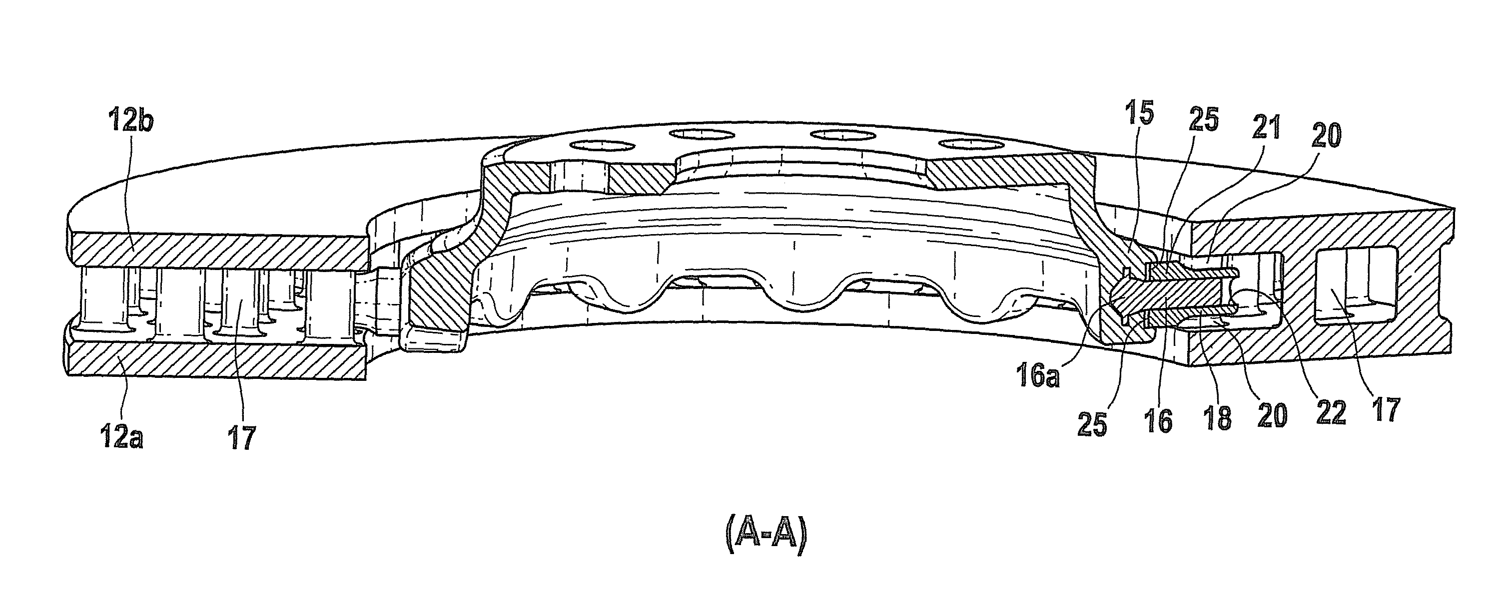
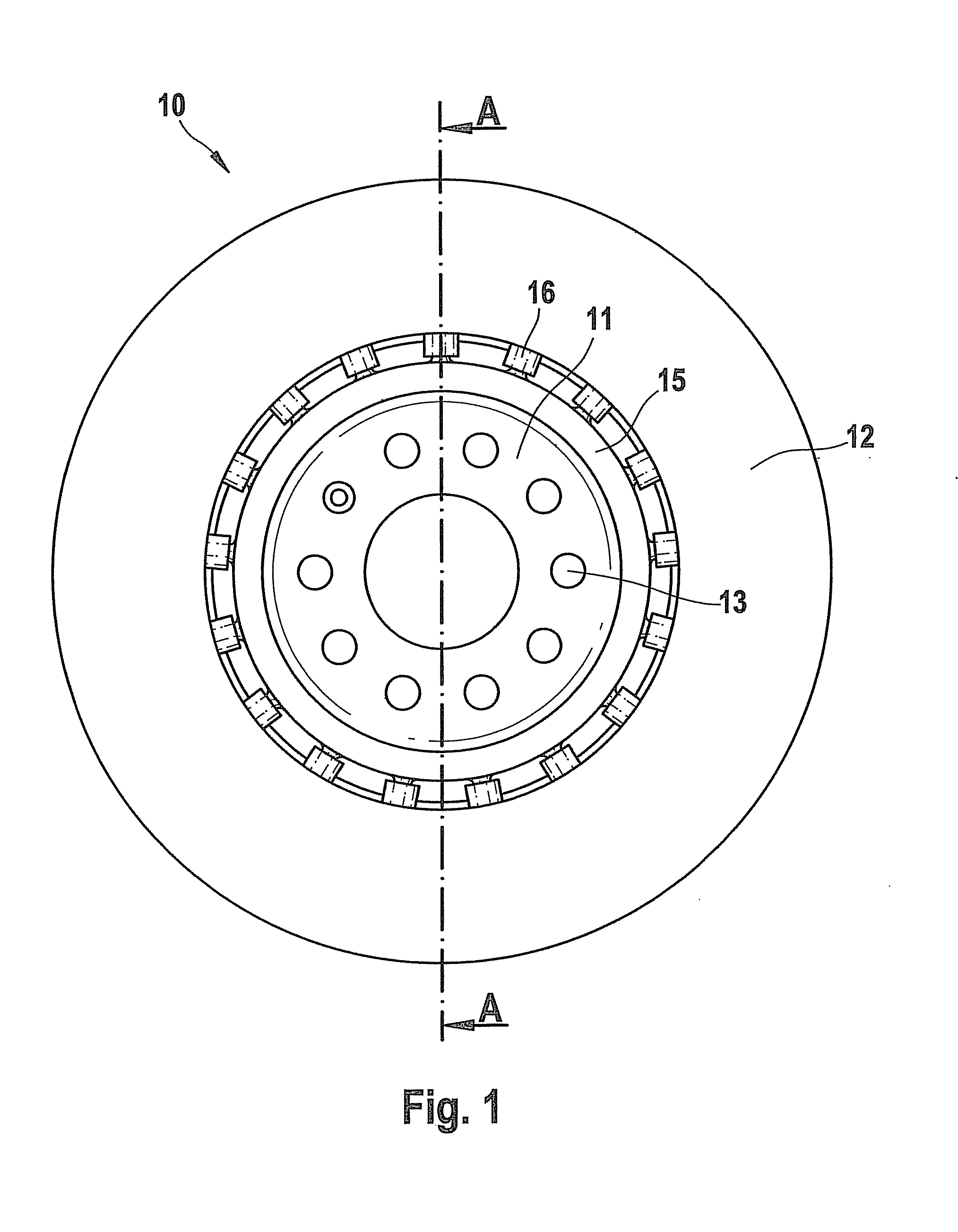
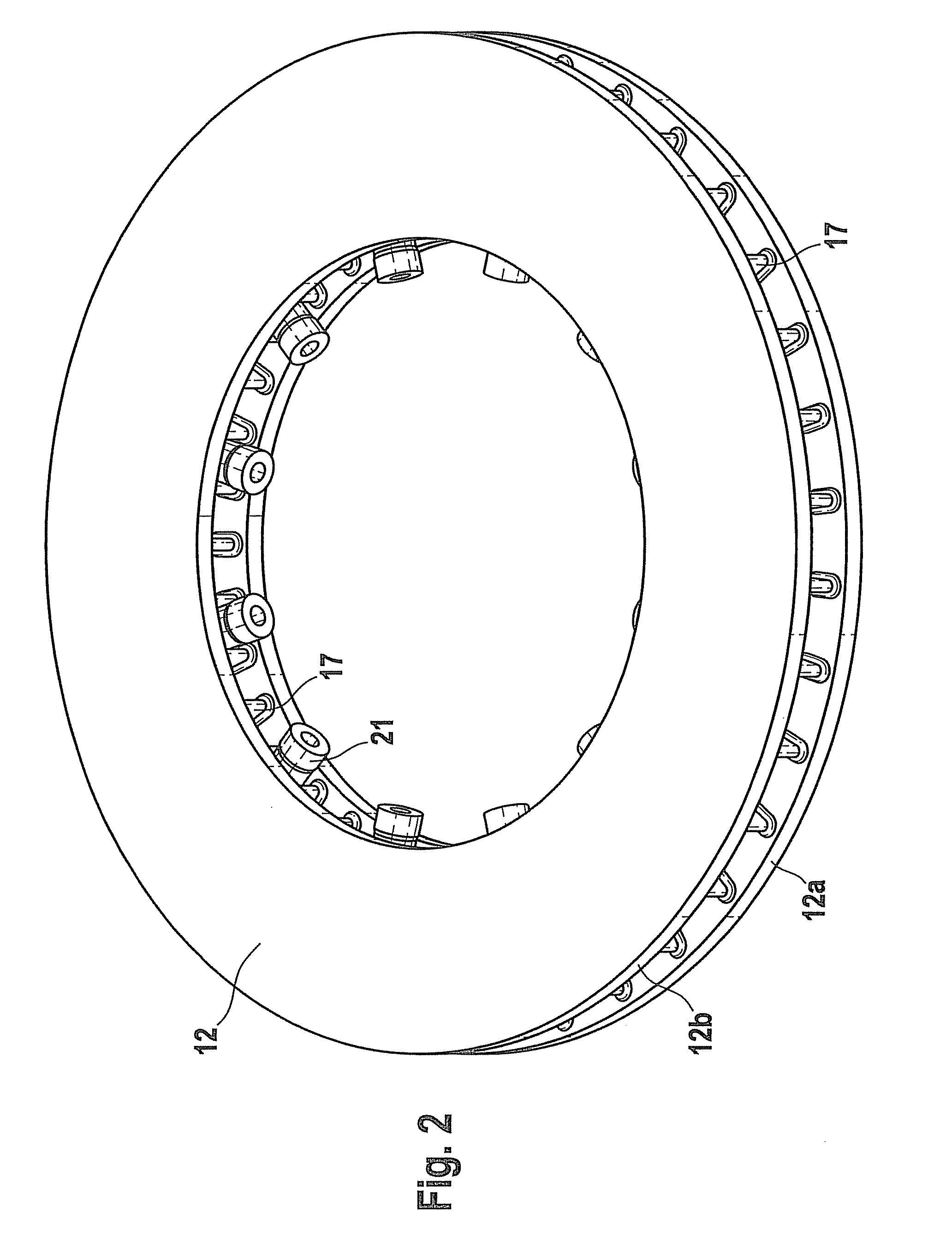
[0009]In FIG. 1, reference character 10 designates a brake disk made up of a disk pot 11 and a friction ring 12. In a conventional manner, disk pot 11 is fastened (in a manner not shown here) on a hub of a vehicle, the fastening screws extending through bores 13 of disk pot 11. Disk pot 11 is connected to friction ring 12 (as is shown in more detail in FIGS. 2 and 3) via a large number of connecting elements 16 formed in circumferential wall 15 of disk pot 11, in the form of pins or bolts or the like. Friction ring 12 is made up of two friction rings 12a and 12b, which are connected to one another by a large number of webs 17 distributed over the circumference, and in particular running in the radial direction, so that a ventilated brake disk results. As can be seen in more detail in FIG. 2 and FIG. 3, bearer webs 18 that run radially are situated on two successive webs 17. Here, bearer webs 18 are situated segment by segment, so that in each case a free web 17 is situated between s...


PUM


Abstract

A brake disk is described that has a friction ring and a disk pot that is connected to the friction ring via connecting elements. On the webs of the friction ring, bearer webs are fashioned into which the connecting elements extend. In addition, the bearer webs are fashioned in such a way that cooling air can flow around them.

Description

FIELD OF THE INVENTION[0001]The present invention relates to a brake disk, in particular a ventilated brake disk, having a friction ring and a bearer part, in particular a disk pot, connected to a friction ring via connecting elements.BACKGROUND INFORMATION[0002]German Patent No. DE 43 32 951 A1 describes a ventilated brake disk that has a friction ring and a bearer part connected to the friction ring by connecting elements. The connecting elements are fashioned in particular as pins, bolts, or the like, and are distributed around the circumference of the bearer part. The connecting elements extend into openings in the circumferential wall of the friction ring. In this way, the friction ring is mounted in “floating” fashion on the disk pot. Here, when there is a rise in temperature caused by the braking process, the connecting elements can expand in the radial direction without danger of warping. However, given larger torques there is the danger that, due to the free length of the c...

Claims


Application Information

Patent Timeline
Patent Type & Authority Patents(United States)
IPC IPC(8): F16D65/12
CPCF16D65/123F16D65/128F16D2065/1392F16D2065/136F16D2065/1328
Inventor MUELLER, HANS-WALTER
Owner ROBERT BOSCH GMBH
Why Eureka
Try Eureka