Cooling plate for an iron- or steelmaking furnace

a technology of cooling plate and iron ore, which is applied in the direction of chamber doors, laminated elements, light and heating apparatus, etc., can solve the problems of inability to achieve far, and achieve the effects of reducing pressure loss, avoiding discontinuities in flow patterns, and pre-determined pressure losses in individual cooling circuits

Inactive Publication Date: 2009-08-20
PAUL WURTH SA
View PDF11 Cites 5 Cited by
  • Summary
  • Abstract
  • Description
  • Claims
  • Application Information

AI Technical Summary

Benefits of technology

[0013]The cooling plate according to the invention comprises a copper cooling plate body (i.e. a cooling plate body made from copper or a copper alloy), with at least one cooling duct, which extends essentially parallel with the back of the cooling plate. At least one connection piece is arranged on the back of the cooling plate body and terminates in the cooling plate body in the at least one cooling duct. According to the invention, the cooling plate has a formed piece, which is fitted in a prefabricated, externally accessible recess in the cooling plate body and forms a deflection surface for the cooling medium in the area of the termination of the connection piece in the cooling duct. The entry of the cooling medium from the connection piece into the cooling duct or from the cooling duct into the connection piece can be improved from the flow point of view in an extremely simple way by this deflection surface. Consequently, the pressure losses in the cooling plate can be substantially reduced, which of course has a favorable effect on the energy consumption for circulation of the cooling medium. The risk of steam bubble formation by high local pressure losses is likewise greatly reduced. Furthermore, escape of the air during filling of the cooling plates with the cooling medium is simplified by the deflection surface according to the invention. In other words, the deflection surfaces according to the invention prevent air pockets from forming in the cooling ducts and causing so-called “hot spots”. It should also be noted that the invention can be applied to cooling plate bodies, which are manufactured by the methods, described in DE-A-2907511 and in WO98 / 30345, with excellent results with regard to reduction of the pressure losses. Consequently these cooling plate bodies can also be used, if low-pressure losses are required, which was so far not possible.
[0014]In an extremely simple embodiment of the invention, the formed piece is arranged in an axial extension of the cooling duct, the deflection surface being formed by one of its end faces. If the cooling duct is formed, for example, by a duct which has an opening in an end face of the cooling plate body, the formed piece is advantageously a plug, which is inserted in this opening and extends into the cooling duct as far as the opening of the connection piece, where it forms the deflection surface for the cooling medium. To improve the transition between the connection piece and the cooling duct from the flow point of view, it is already sufficient that the deflection surface is formed by a bevelled end of the formed piece. Deflection surfaces optimised from the flow point of view with a concave curvature naturally permit further reduction of the local pressure loss.
[0016]These cooling plates with inserted transition pieces likewise have the advantage that the transition between the connection piece and the cooling duct is always formed identically by a standardized prefabricated transition piece, so that the pressure losses in the individual cooling circuits can be predetermined and coordinated far more easily. The transition pieces are also preferable from the mechanical point of view to direct welding or soldering in of a connection piece into a hole in the cooling plate body.
[0017]Reduction of the pressure loss by the transition piece according to the invention is particularly pronounced for cooling plate bodies with cooling ducts, which have an oblong cross-section. In these cooling plates the transition from the oblong cross-section of the cooling duct to a circular cross-section in the coolant connection is in fact effected progressively in the curved transition duct of the transition piece, so that discontinuities in the flow pattern are avoided.
[0018]The transition piece advantageously has a solid shoulder, which forms a spacer which projects from the back of the cooling plate. In the assembled cooling plate these shoulders simultaneously press a seal into the bushing of the connection pieces in the furnace shell. It is thus unnecessary to weld or solder an additional element around the connection piece to the back of the cooling plate, so that the cooling plate production process is simplified. Furthermore, a relatively solid shoulder on the transition piece facilitates assembly of the connection piece.
[0020]The recess for the transition piece advantageously terminates in one end of the cooling plate body. Consequently it can be manufactured more easily and the cooling duct can extend to a point immediately adjacent to the end of the cooling plate body. Furthermore, it should be noted in relation to this embodiment of the invention that the transition piece closes and seals the cooling duct at the end. Consequently the soldering or welding of plugs into the cooling ducts open at the ends described in DE-A-2907511 and WO98 / 30345 is dispensed with, so that a further operating step is saved.

Problems solved by technology

Consequently these cooling plate bodies can also be used, if low-pressure losses are required, which was so far not possible.

Method used


Image

  • Cooling plate for an iron- or steelmaking furnace
  • Cooling plate for an iron- or steelmaking furnace
  • Cooling plate for an iron- or steelmaking furnace

Examples


Embodiment Construction

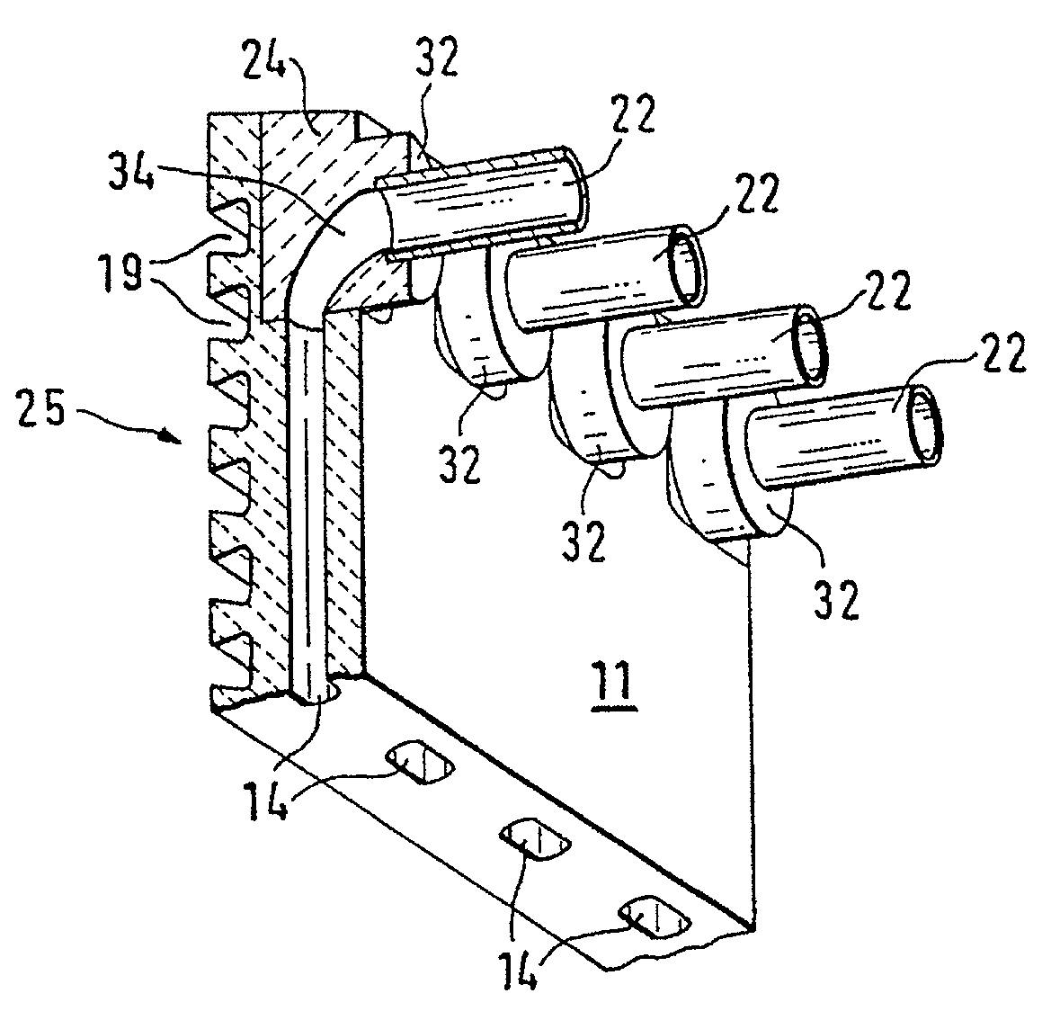
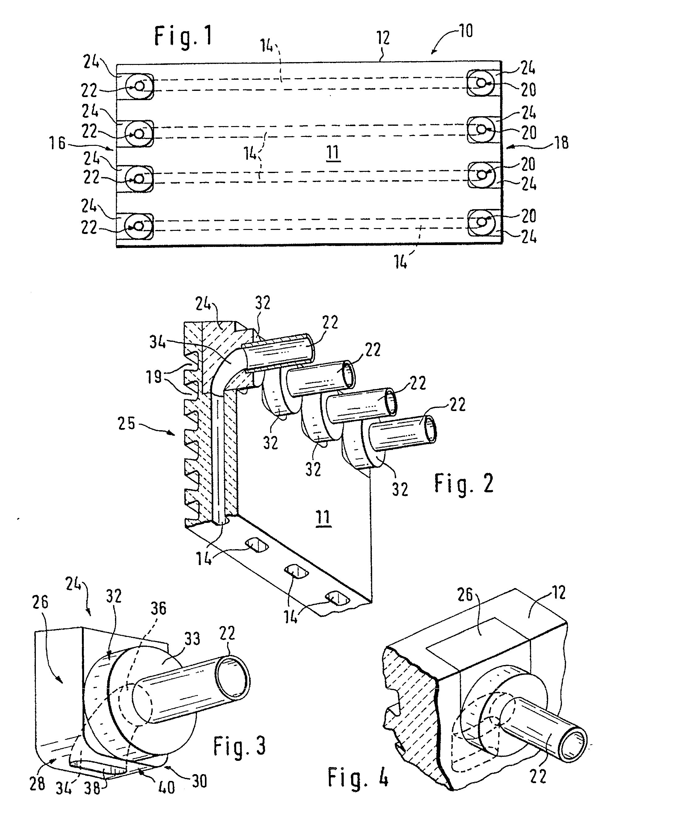
[0032]The cooling plate 10 shown consists essentially of a cooling plate body 12 made from copper or a copper alloy with a rectangular surface. Four straight cooling ducts 14, which extend parallel with the surface through the cooling plate body 12 from one end 16 to the opposite end 18, are integrated in the cooling plate body 12. This cooling plate body 12 was advantageously manufactured by the method described in the subsequently published patent application WO 98 / 30345. A preform of the cooling plate body 12 was continuously cast in a continuous casting mould, whereby rod-type inserts in the casting duct produced ducts running in the casting direction, which form the cooling ducts 14. As shown in FIG. 2 the cross-section of the integrally cast ducts 14 has an oblong shape with its smallest dimension at right angles to the plate. A plate was cut out of this continuously cast preform by two cuts at right angles to the casting direction, the two end faces 16 and 18 of the cooling p...


PUM

PropertyMeasurementUnit
refractoryaaaaaaaaaa
thermal conductivityaaaaaaaaaa
porosityaaaaaaaaaa

Abstract

A cooling plate for an iron and steelmaking furnace includes a copper cooling plate body having at least one cooling duct for a cooling medium extending essentially parallel with the back of the cooling plate body. The cooling plate body further includes a preformed, externally accessible recess into which the cooling duct opens. A connection piece is utilized as a cooling medium connection on the back of the cooling plate body, while a formed piece fitted within the externally accessible recess forms a deflection surface for the cooling medium flowing from the connection piece into the cooling duct, or from the cooling duct into the connection piece.

Description

CROSS REFERENCE TO RELATED APPLICATIONS[0001]This application is entitled to the benefit of International Application No. PCT / EP1999 / 08735, filed on Nov. 12, 1999, Luxembourg Patent Application No. LU 90328, filed on Dec. 16, 1998 and is a Divisional application of U.S. Non-Provisional Application No. Ser. No. 09 / 868,117, filed on Aug. 20, 2001, now U.S. Pat. No. ______.FIELD OF THE INVENTION[0002]The invention relates to a cooling plate for an iron- or steelmaking furnace.BACKGROUND OF THE INVENTION[0003]Such cooling plates are arranged on the inside of the furnace shell and have internal cooling ducts. These cooling plates are connected via connection pieces projecting from their back to a cooling system of the shaft furnace outside the furnace shell. Their surface facing the interior of the furnace is generally lined with a refractory material.[0004]Most of these cooling plates are still made from cast iron. As copper has a far better thermal conductivity than cast iron; however,...

Claims


Application Information

Patent Timeline
Patent Type & Authority Applications(United States)
IPC IPC(8): F23M5/08F28F3/12B21D53/04C21B7/10F27D1/12F28F9/26
CPCC21B7/10F28F3/12Y10T29/4935Y10T29/49364F28F9/26
Inventor SCHMELER, ROBERTSOLVI, MARCTHILL, ROGER
Owner PAUL WURTH SA
Why Eureka
Try Eureka