Light-emitting diode streetlight structure

a technology of led streetlights and diodes, which is applied in the direction of fixed installation, lighting and heating equipment, lighting support devices, etc., can solve the problems of frequent replacement of power supplies, large amount of heat generated, and the life of led streetlight power supplies can be substantially reduced, so as to reduce the temperature of led streetlights, the effect of reducing the heat generated, and enhancing the heat dissipation of power supplies

Inactive Publication Date: 2013-09-03
OPTO TECH
View PDF8 Cites 4 Cited by
  • Summary
  • Abstract
  • Description
  • Claims
  • Application Information

AI Technical Summary

Benefits of technology

[0009]An objective of the present invention is to provide an LED streetlight structure. According to the present invention, the housing contacting the power supply has a heat dissipating structure, which can dissipate the heat generated by the power supply and reduce the temperature thereof. Accordingly, heat dissipation of the power supply is enhanced, and hence increasing its lifetime.
[0010]Another objective of the present invention is to provide an LED streetlight structure having an angle adjusting structure. By means of the angle adjusting structure, the angle of a lamppost can be adjusted for changing the lighting angle and direction of the light emitted by the LED streetlight structure, and hence achieving an ideal lighting performance.

Problems solved by technology

The lighting market is long considered as the greatest and potential market of LEDs, even though no major lighting product is proposed owing to cost and performance limitations.
However, it is undeniable that LED technology has been developing rapidly in recent years, making it to occupy some market in the special light market, such as the niche markets of freezer lighting, aviation lamps, or traffic lights).
It is because LEDs generate a huge amount of heat.
Besides, the lifetime of the power supply of the LED streetlight can be also substantially reduced caused by long-term overheating applications, and hence leading to frequent replacement of power supplies.
Moreover, the lighting angle and direction of current LED streetlight are fixed, and therefore they cannot be adjusted according to the environment during installation.

Method used


Image

  • Light-emitting diode streetlight structure
  • Light-emitting diode streetlight structure
  • Light-emitting diode streetlight structure

Examples


Embodiment Construction

[0018]In order to make the structure and characteristics as well as the effectiveness of the present invention to be further understood and recognized, the detailed description of the present invention is provided as follows along with embodiments and accompanying figures.

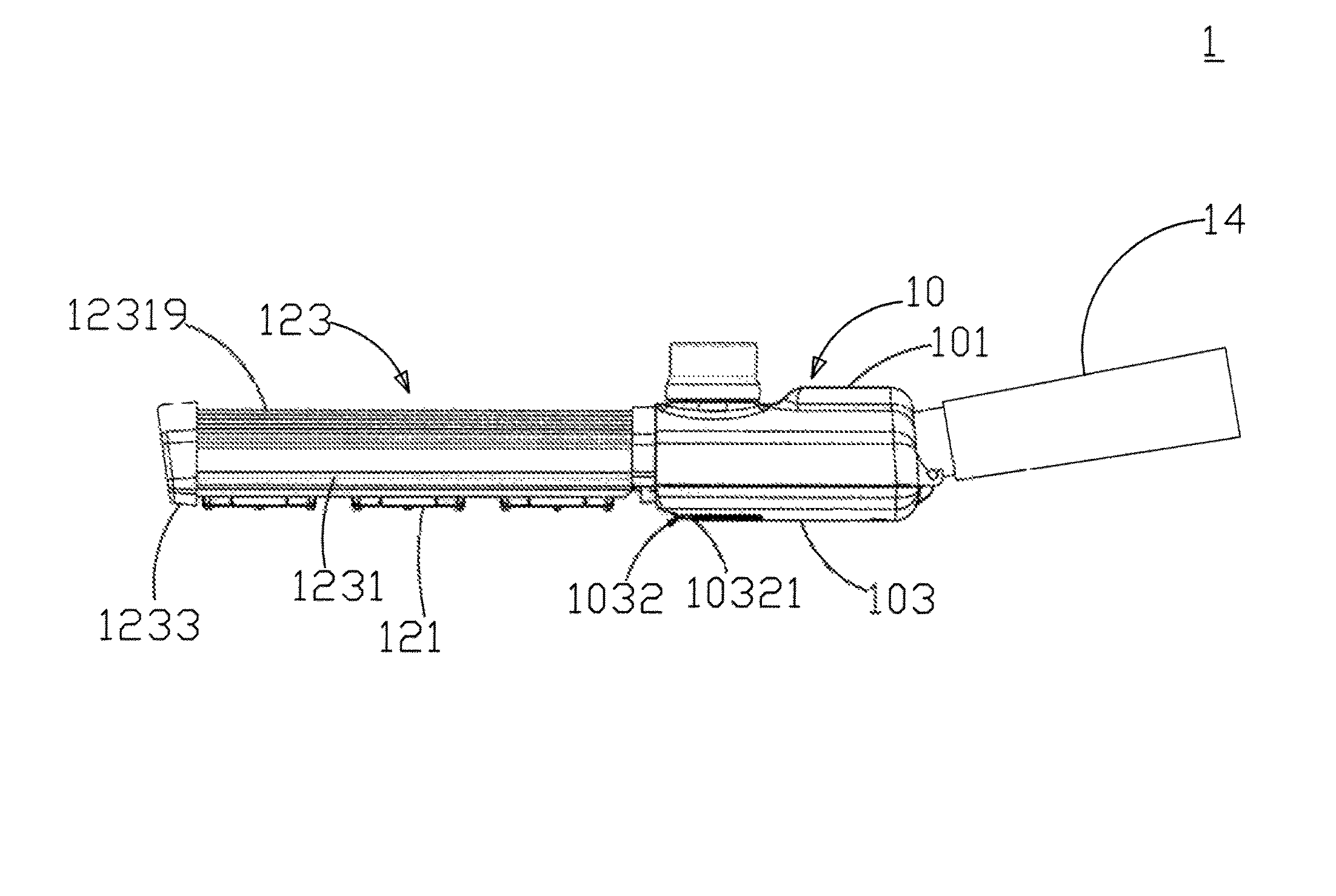
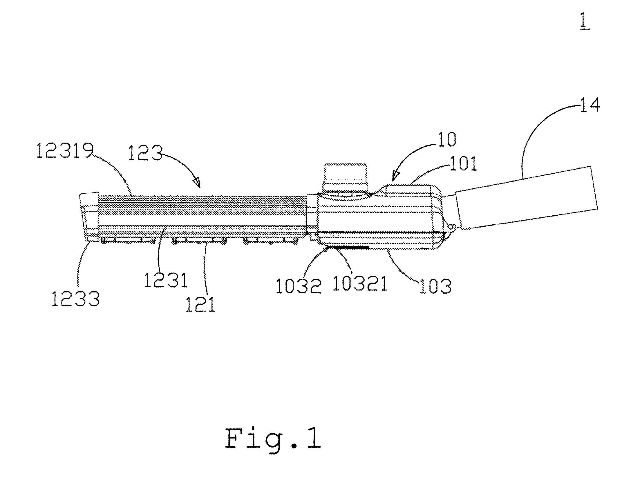
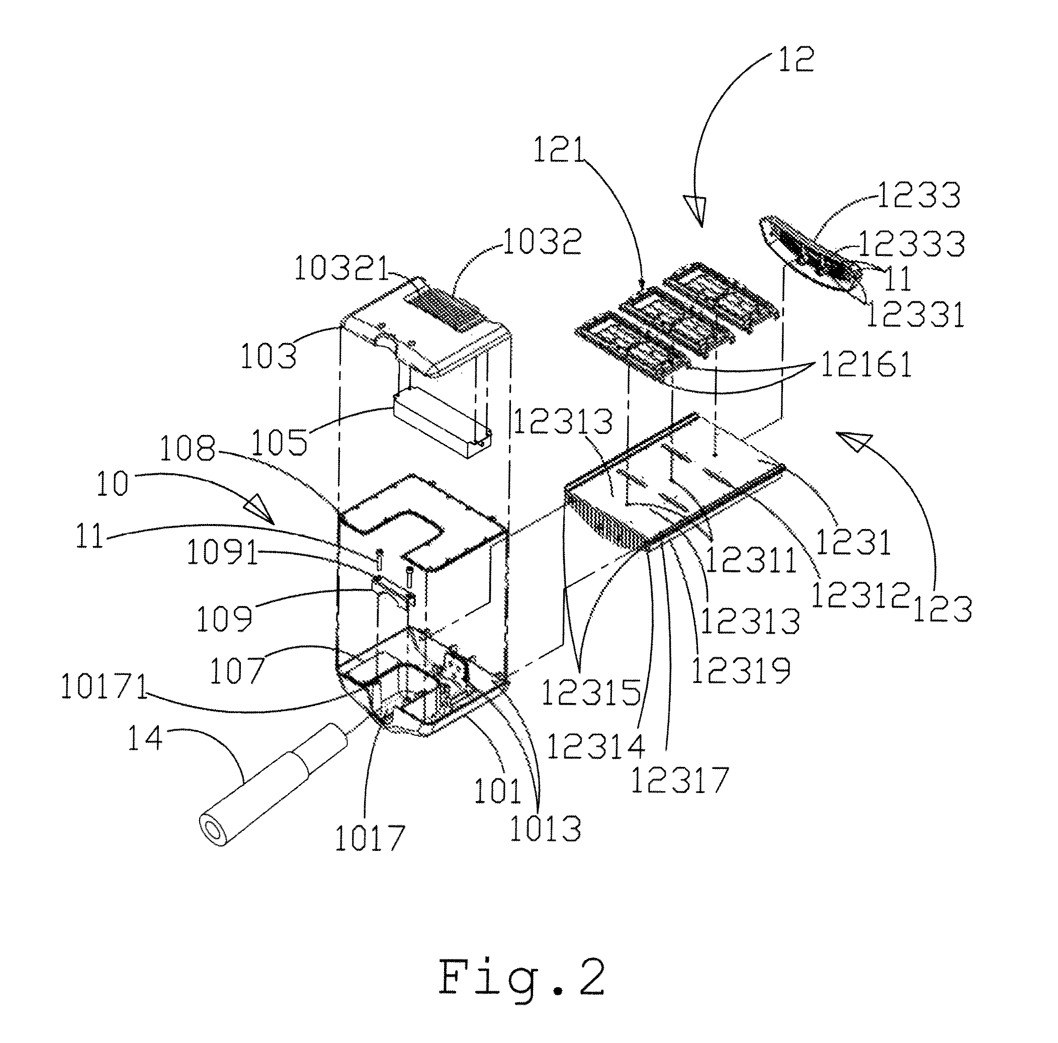
[0019]FIG. 1 shows a three-dimensional view of the LED streetlight structure according to a preferred embodiment of the present invention. As shown in the figure, the present invention provides an LED streetlight structure 1, which comprises a power module 10, a light-emitting module 12, and a lamppost 14. The light-emitting module 12 is disposed on one side of the power module 10. The lamppost is disposed on the other side of the power module 10 and corresponds to the light-emitting module 12. FIG. 2 shows an exploded view of the LED streetlight structure according to a preferred embodiment of the present invention. As shown in the figure, the power module 10 comprises a first housing 101, a second housing 103, a ...


PUM


Abstract

A light-emitting diode (LED) streetlight structure, which includes a light-emitting module, a power module, and a lamppost. The light-emitting module is disposed on side of the power module; the lamppost is disposed on the other side of the power module and corresponds to the light-emitting module. A heat-dissipating structure is disposed on the surface of a housing of the power module. The heat-dissipating structure corresponds to a power supply in the power module, and can dissipate the heat generated by the power supply and reduce the temperature thereof. Accordingly, heat dissipation of the power supply is enhanced, and hence increasing its lifetime.

Description

FIELD OF THE INVENTION[0001]The present invention relates generally to a streetlight structure, and particularly to a light-emitting diode (LED) streetlight structure with excellent heat-dissipation and lighting performance.BACKGROUND OF THE INVENTION[0002]LEDs are diodes capable of emitting light when forward biased. They are light-emitting devices manufactured by semiconductor materials mostly including III-V chemical elements, such as gallium phosphide or gallium arsenide in the early days and aluminum-gallium-indium phosphide or gallium-indium nitride for high-brightness LEDs at present day. The light-emitting principle is to apply a current to the compound semiconductor. Then part of the energy will be released in the form of light via recombination of electrons and holes and thus achieving light-emitting effect.[0003]Because the used materials are different, the energy levels of electrons and holes in LEDs differ. When the electrons and holes recombine, the released photons wi...

Claims


Application Information

Patent Timeline
Patent Type & Authority Patents(United States)
IPC IPC(8): F21V29/00
CPCF21S8/086F21V23/008F21V21/116F21V29/763F21W2131/103
Inventor LIN, WAN-CHIHTAI, YI-MINGYANG, CHENG-WEIWU, CHIA-WENCHEN, SHUN-CHIH
Owner OPTO TECH
Why Eureka
Try Eureka