Underwater and landscape lighting system

a lighting system and landscape technology, applied in outdoor lighting, outdoor lighting, lighting applications, etc., can solve the problems of led elements failing after a shorter operating life, large amount of heat generated by lighting elements, and degradation of the performance and longevity of lighting systems, so as to reduce the risk of led elements failing, the effect of dissipating heat generated

Inactive Publication Date: 2012-05-03
FUSION RDI INDS
View PDF7 Cites 39 Cited by
  • Summary
  • Abstract
  • Description
  • Claims
  • Application Information

AI Technical Summary

Benefits of technology

[0006]In another aspect, a preferred heatsinkless lighting system for mounting to a standard pool fitting and being submerged in water is disclosed. The heatsinkless lighting system includes a curved lens, a base, a circuit board and an adaptor. The curved lens has an exterior side and an interior side. The base is sealingly coupled to the interior side of the curved lens and has one or more connector members. The circuit board is coupled to the base such that the circuit board is sealed between the curved lens and the base. The circuit board implements a circuit comprising a plurality of lighting elements spaced apart from one another on the circuit board to dissipate heat generated by operation of the plurality of lighting elements. The adaptor is configured to mount the heatsinkless lighting system to a standard pool fitting such that the water surrounds the lens and base to dissipate the heat created during use of the plurality of lighting elements. The adaptor has one or more hook members configured to engage with the one or more connector members of the base.
[0007]In yet another aspect, a heatsinkless lighting system for mounting to a standard pool fitting and being submerged in water is described. The heatsinkless lighting system includes a lens, a base, a circuit board and an adaptor. The lens is curved and has an exterior side and an interior side. The base has a first side and a second side and is sealingly coupled to the curved lens. The second side of the base has two or more snap connector members and a threaded coupling arranged thereon. The circuit board is coupled to the first side of the base such that the circuit board is sealed between the curved lens and the base. The circuit board implements a circuit comprising a plurality of lighting elements spaced apart from one another on the circuit board to dissipate heat generated by operation of the plurality of lighting elements. The adaptor is configured to mount the heatsinkless lighting system to a standard pool fitting extending from a wall of the pool such that the lens and base are surrounded by water to dissipate the heat from use of the plurality of lighting elements. The adaptor has two or more hook members configured to engage with the one or more snap connector members of the base.

Problems solved by technology

Operation of such lighting systems causes the lighting elements to generate large amounts of heat.
Build up of heat within the lighting system (e.g., from the lighting element(s), microcontroller(s) and any other circuit elements) results in degradation in the performance and longevity of the lighting system.
Where the lighting elements are light emitting diodes (“LEDs”), higher operating temperatures may result in the LED elements failing after a shorter operating lifespan.
The trend toward brighter lighting systems, using simultaneous combinations of active light elements, as well as the use of higher power light elements, exacerbates the heat problem.
While water within the water-bearing body provides some cooling, it is insufficient to properly cool the lighting system because the water is typically still within the water-bearing body.
Further, the temperature of the water is typically not sufficiently cold to cool an operating lighting system, especially in warmer climates.
However, such heatsinks increase the component and manufacturing cost of the lighting system.
In addition, these heatsinks are often relatively large, because they are located within a fitting inside a cavity in the wall of a pool where air and / or water circulation is relatively low.

Method used


Image

  • Underwater and landscape lighting system
  • Underwater and landscape lighting system
  • Underwater and landscape lighting system

Examples


Embodiment Construction

[0018]Certain terminology is used in the following description for convenience only and is not limiting. The words “right,”“left,”“lower,” and “upper” designate directions in the drawings to which reference is made. The words “inwardly” or “distally” and “outwardly” or “proximally” refer to directions toward and away from, respectively, the geometric center or orientation of the device and instruments and related parts thereof. The terminology includes the above-listed words, derivatives thereof and words of similar import.

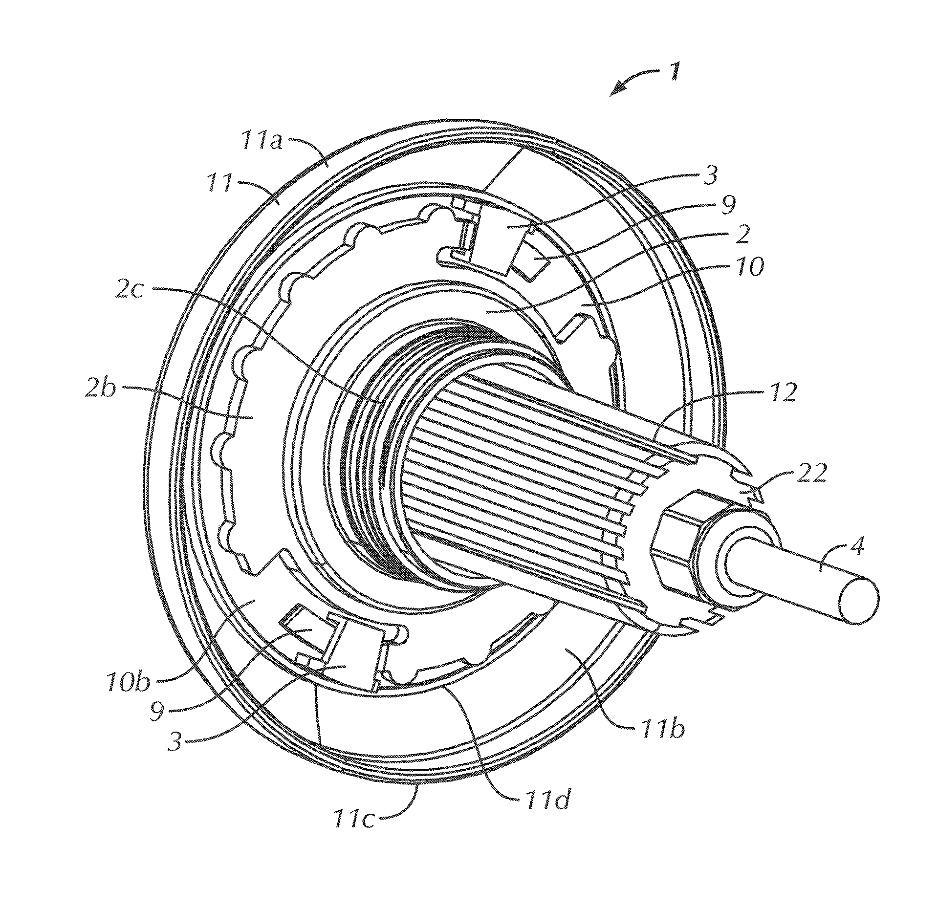
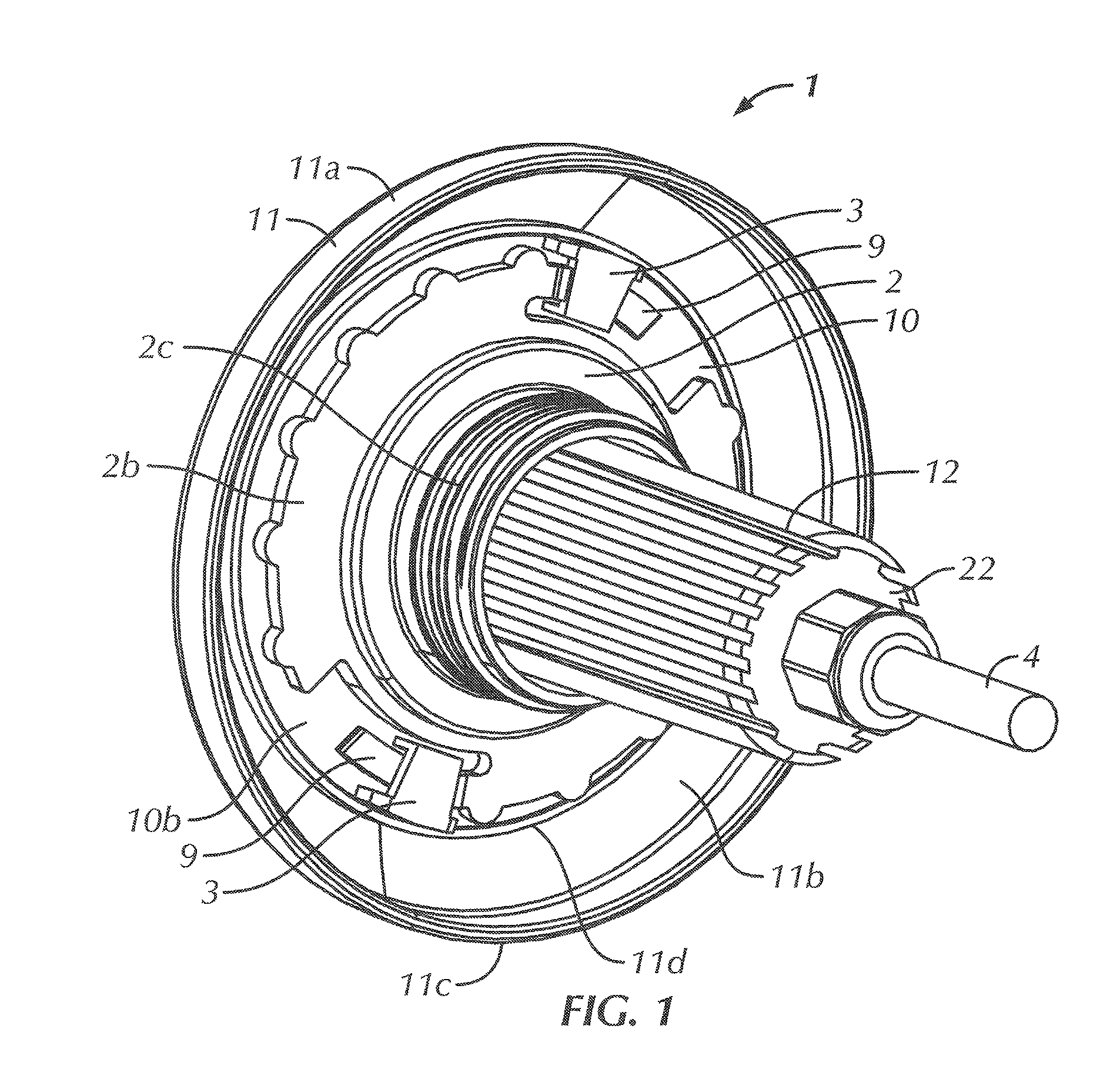
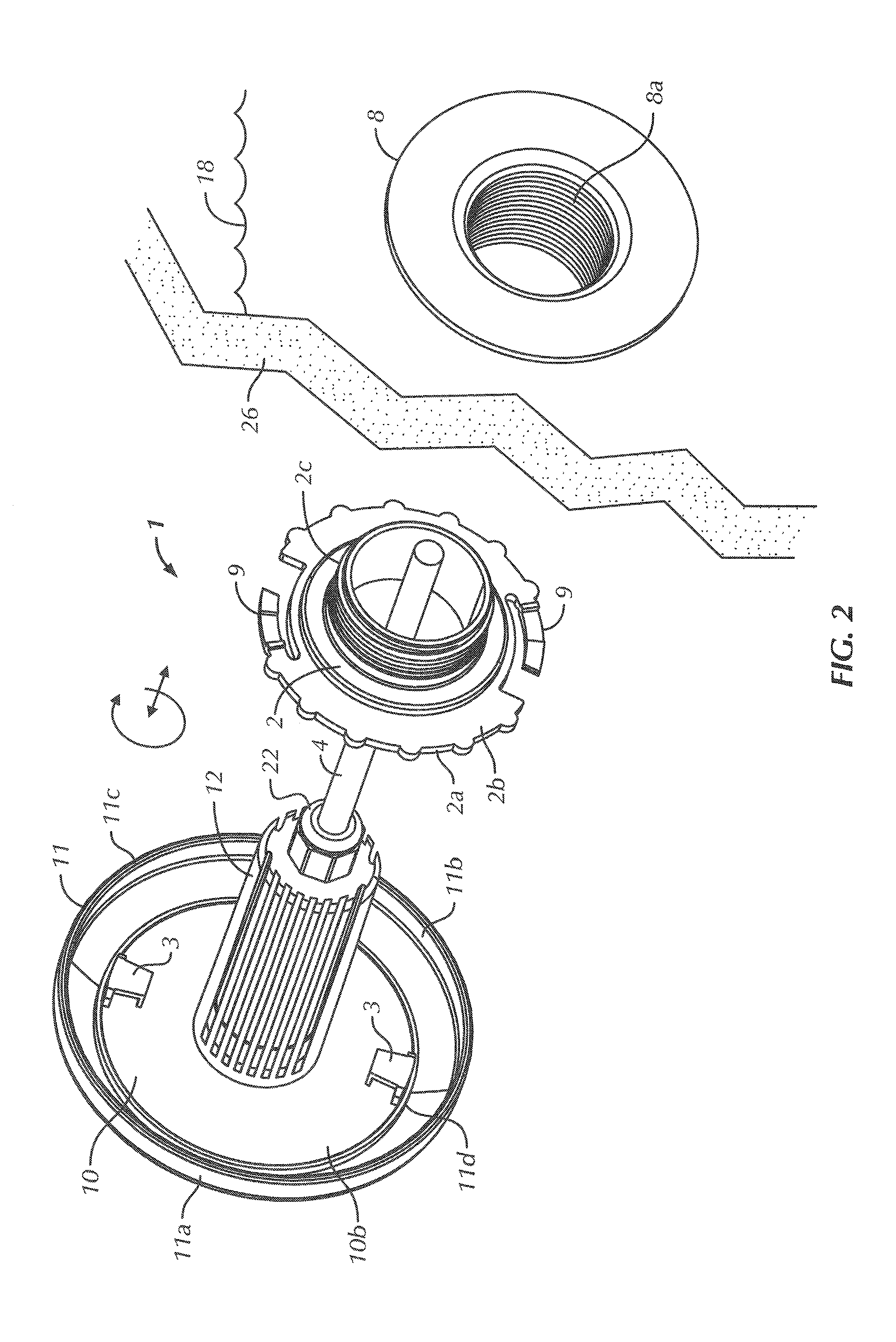
[0019]Although the present invention can be used in conjunction with any type of indoor or outdoor application, it is especially suited for underwater lighting applications in connection with pools, spas, baths, fountains, aquariums and the like. Accordingly, the present invention will be described herein with reference to swimming pool applications, particularly for mounting the lighting system to a standard one and one-half inch (1.5″) threaded pool fitting. How...


PUM


Abstract

A lighting system is described. The lighting system includes a substantially round lens, a base, a circuit board and an adaptor. The lens has an exterior side and an interior side. The base has a first side and a second side. The base is sealingly coupled to the interior side of the lens to create a watertight compartment therebetween. The second side of the base has at least one connector member. The circuit board is coupled to the first side of the base. The circuit board implements a circuit including a plurality of light emitting diodes (“LEDs”) and a power supply receiving connector. The power supply receiving connector is accessible through the second side of the base. The adaptor has a first side configured to interface with the at least one connector member and a second side having a threaded coupling to maintain the lighting system in a fixed position in a fitting.

Description

CROSS-REFERENCE TO RELATED APPLICATIONS[0001]This application claims priority to U.S. Provisional Patent Application No. 61 / 409,491, filed Nov. 2, 2010, which is incorporated herein by reference in its entirety.BACKGROUND OF THE INVENTION[0002]It is frequently desirable to illuminate water-bearing bodies such as swimming pools, spas, hot tubs and fountains from below the water line. In these applications, lighting systems are often installed on and / or in the surfaces of the water-bearing body by coupling the lighting systems to a niche or other fitting. Such niches come in a plurality of sizes to accommodate lighting systems of various sizes. These lighting systems typically include a glass or plastic external lens, one or more lighting elements or light emitters, a circuit board, and one or more components for mounting the lighting system to the surface of the water-bearing body such that the external lens faces into the water-bearing body, and is exposed to the water contained the...

Claims


Application Information

Patent Timeline
Patent Type & Authority Applications(United States)
IPC IPC(8): F21V5/04F21V29/00
CPCF21S8/081F21V3/04F21V19/003F21V19/0055F21V21/02F21V21/0824F21S8/024F21W2131/109F21W2131/401H05B37/029F21V29/58F21Y2115/10F21V31/005H05B47/155
Inventor BOA, STEVE
Owner FUSION RDI INDS
Why Eureka
Try Eureka