LED lamp

a technology of led lamps and led lamps, which is applied in the direction of fixed installation, semiconductor devices for light sources, lighting and heating apparatus, etc., can solve the problems of inconvenient assembly and maintenance of led lamps, complex structure of led lamps,

Inactive Publication Date: 2010-12-30
FU ZHUN PRECISION IND SHENZHEN +1
View PDF20 Cites 38 Cited by
  • Summary
  • Abstract
  • Description
  • Claims
  • Application Information

AI Technical Summary

Problems solved by technology

Thus, the structure of the LED lamp is complex.
The ass

Method used


Image

  • LED lamp
  • LED lamp
  • LED lamp

Examples


Embodiment Construction

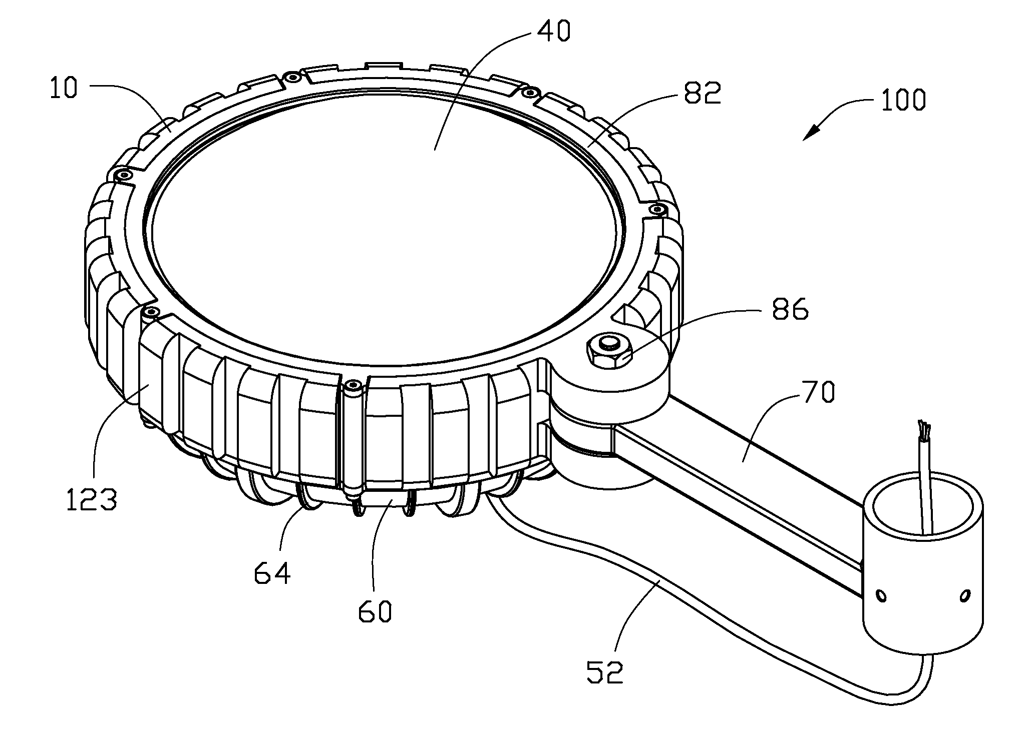
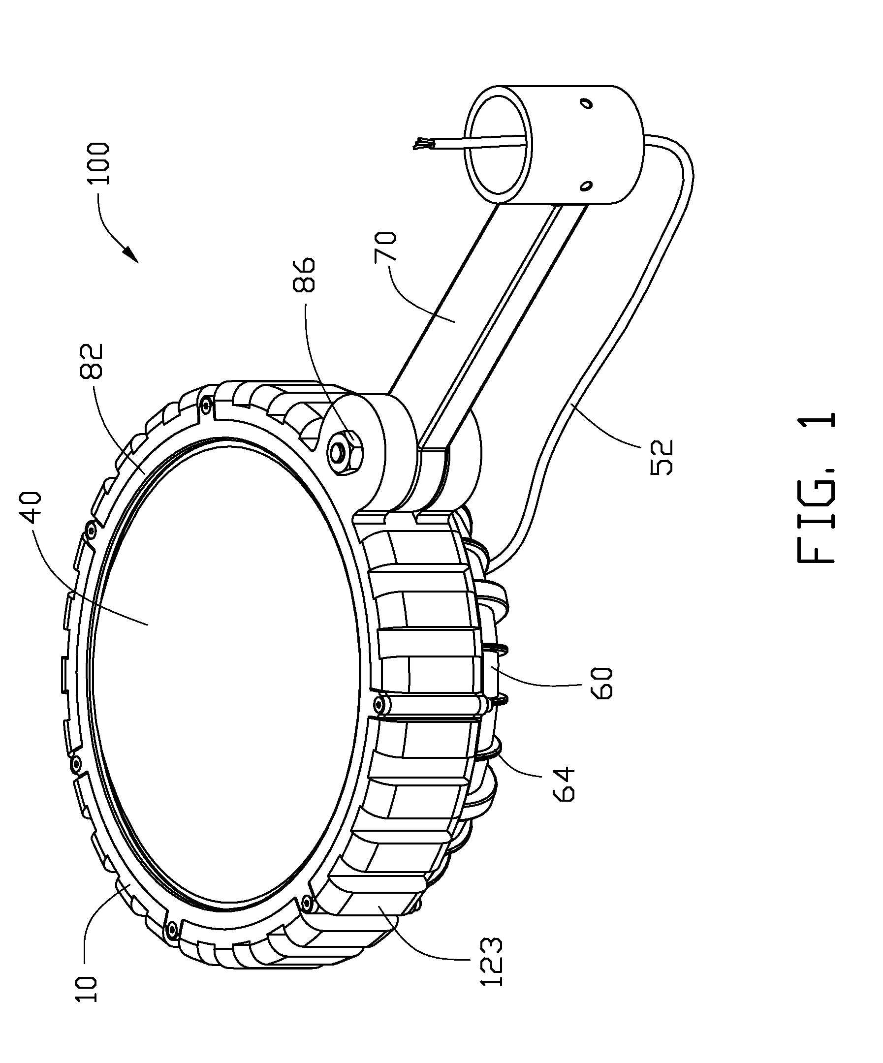
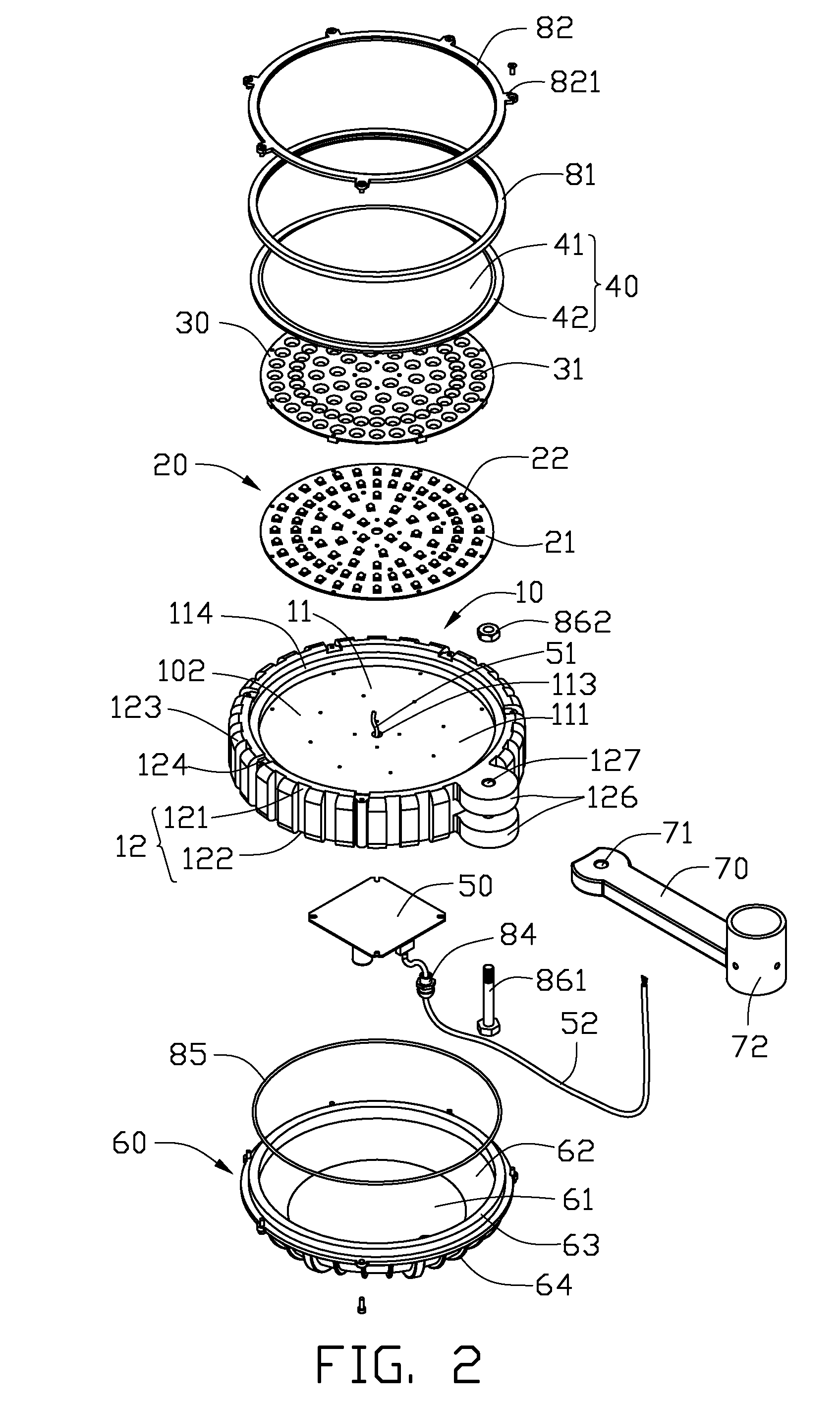
[0012]Referring to FIGS. 1 and 2, an LED lamp 100 according to an exemplary embodiment includes a heat sink 10, an LED module 20, a reflecting plate 30, a lamp cover 40, a driving circuit module 50, a rear cover 60 and a connecting member 70. The LED module 20, the reflecting plate 30 and the lamp cover 40 are arranged at a front end of the heat sink 10, while the driving circuit module 50 and the rear cover 60 are arranged at a rear end of the heat sink 10. The connecting member 70 is connected to a peripheral edge of the heat sink 10.

[0013]The heat sink 10 is substantially a flat cylinder. In other words, the heat sink 10 has a diameter greater than a height thereof. The heat sink 10 is made of metal having a high thermal conductivity, such as copper or aluminum. Referring also to FIG. 4, the heat sink 10 defines first and second cavities 102, 104 at the front end and the rear end, respectively. The heat sink 10 includes a circular base 11 isolating the first cavity 102 from the s...


PUM


Abstract

An LED lamp includes a heat sink, an LED module, a lamp cover, a driving circuit module and a rear cover. The heat sink defines isolated first and second cavities in two opposite ends thereof. The LED module is received in the first cavity of the heat sink and connecting with the heat sink. The lamp cover is arranged at an opening of the first cavity and covering the LED module. The driving circuit module is received in the second cavity of the heat sink and electrically connecting with the LED module. The rear cover is arranged at an opening of the second cavity of the heat sink and covering the driving circuit module.

Description

BACKGROUND[0001]1. Technical Field[0002]The present disclosure relates to light emitting diode (LED) lamps, and particularly to an LED lamp with a simple structure and having high heat dissipating efficiency.[0003]2. Description of Related Art[0004]The technology of LED has been rapidly developed in recent years from indicators to illumination applications. LEDs are widely used in many fields due to their excellent properties, including environment friendliness, low power consumption, long-term reliability, and et al.[0005]Generally, an LED lamp includes a plurality of LEDs, a driving circuit module for activating the LEDs and controlling the brightness and color blending of the LED lamp, and a heat sink for dissipating heat generated by the LEDs. In order to assembly the components of the LED lamp together, the LED lamp is designed to a complex structure. Further, an additional receiving member is provided to receive the driving circuit module, to thereby make sure of the electrica...

Claims


Application Information

Patent Timeline
IPC IPC(8): F21V29/00
CPCF21S8/08F21V23/00F21Y2101/02F21W2131/103F21Y2105/001F21V29/004F21Y2105/10F21Y2115/10F21V29/71
Inventor ZHANG, WEN-XIANG
Owner FU ZHUN PRECISION IND SHENZHEN
Why Eureka
Try Eureka