Cooling heat-generating electronics

a technology for electronic devices and cooling systems, applied in the direction of electrical apparatus contruction details, electrical apparatus casings/cabinets/drawers, instruments, etc., can solve the problems of high power consumption, failure of one or more electronic devices on the tray, power consumption and electronics operation may also generate heat,

Active Publication Date: 2012-06-07
GOOGLE LLC
View PDF15 Cites 39 Cited by
  • Summary
  • Abstract
  • Description
  • Claims
  • Application Information

AI Technical Summary

Benefits of technology

[0014]In one or more specific aspects of one or more of the general implementations, the changed phase-change material may substantially fill an air gap between the portion of the plurality of heat-generating electronic devices and the heat sink.
[0015]In one or more specific aspects of one or more of the general implementations, the changed phase-change material may substantially fill an air gap between the motherboard and the heat sink.
[0033]Various implementations of a server rack tray assembly according to the present disclosure may include one or more of the following features and / or advantages. For example, the tray assembly may allow for more effective convection cooling by relocating heat generated by electronics devices to an area with a cooling airflow over or by the tray assembly. The tray assembly may also provide for cooling of heat generating devices on the tray through conductive transfer away from a hard-to-cool area of the tray. The tray assembly may also mix conductive and convective cooling techniques to whisk heat away from hard-to-cool areas of the tray. As another example, the tray assembly may help prevent failures, and even catastrophic failures, of one or more electronic devices due to overheating even with little to no significant airflow around the devices. The tray assembly may use conductive and convective heat transfer techniques in series and / or parallel heat transfer operations to cool devices that are provided with little to no airflow. The tray assembly may also use radiative heat transfer techniques to dissipate heat generated by devices that are provided with little to no airflow.
[0034]Various implementations of a server rack tray assembly according to the present disclosure may also include one or more of the following features and / or advantages. For example, the tray assembly may provide for a plug-in thermal solution (or thermal transfer system) that communicates some or all of the heat generated by one or more heat-generating components from a vicinity with limited or no forced convection to a vicinity with substantial forced convection. For instance, the heat may be communicated to a more favorable location on the tray assembly if forced convection is not available or limited in the vicinity of the one or more components. Further, the tray assembly may communicate heat to the vicinity that experiences forced air convection depending on the degree to which the components experience air convection. As one example, if the components experience air convection, the plug-in thermal solution may function similar to a traditional heat sink device, in which the heat generated by the components is transferred to the air (e.g., by one or more fins of the thermal solution). However, if there is no airflow (natural convection) near or over the components, the majority of the heat may be transported to a more favorable location (e.g., brackets or tray sides) where forced convection is available. In addition, if there is no airflow (natural convection) near or over the components, the majority of the heat may be transported to a more favorable location (e.g., brackets or tray sides) where natural convection is available

Problems solved by technology

Many forget that this speed often comes with a cost—higher power consumption.
Power consumption and electronics operation may also generate heat.
In some instances, one or more components or devices on a server tray may be located in a difficult-to-cool area of the tray; for example, an area where forced convection is not particularly effective or not available.
The consequence of inadequate and / or insufficient cooling may be the failure of one or more electronic devices on the tray due to a temperature of the device exceeding a maximum rated temperature.
While certain redundancies may be built into a computer data center, a server rack, and even individual trays, the failure of devices due to overheating can come at a great cost in terms of speed, efficiency, and expense.

Method used


Image

  • Cooling heat-generating electronics
  • Cooling heat-generating electronics
  • Cooling heat-generating electronics

Examples


Embodiment Construction

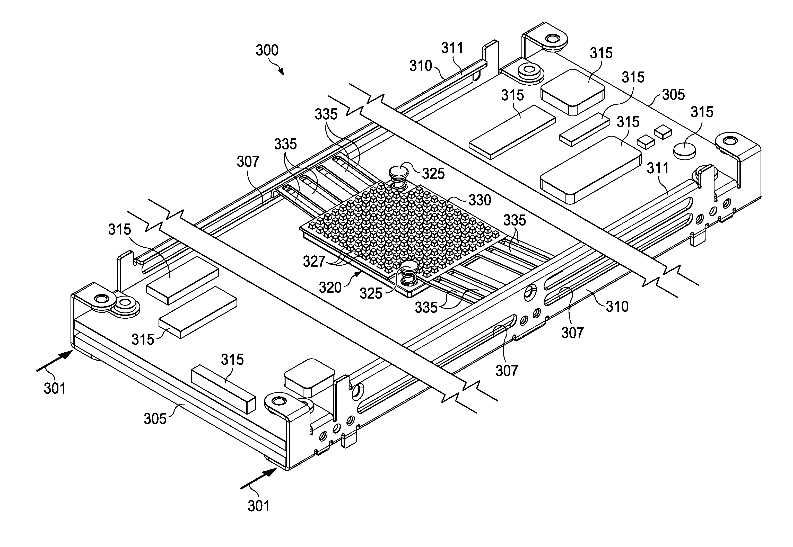
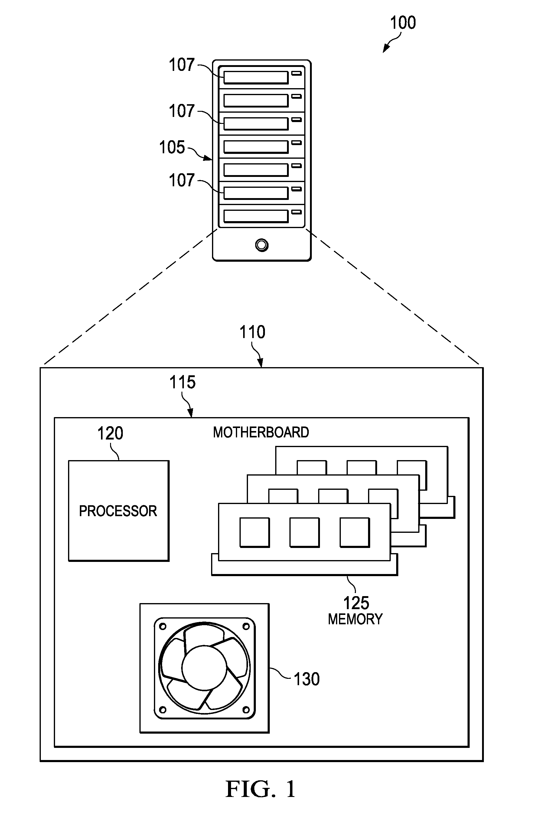
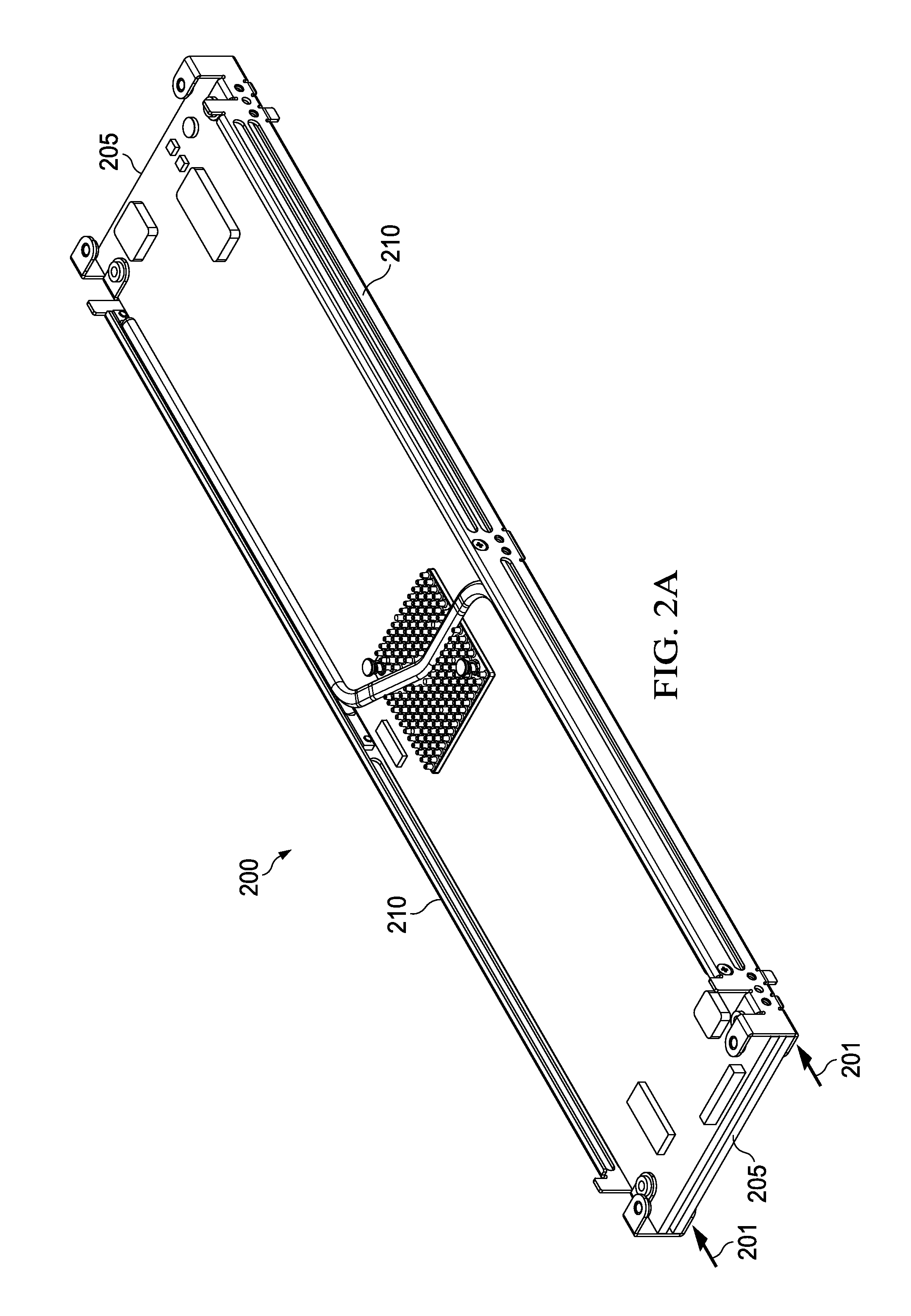
[0040]This document discusses cooling devices that may be implemented as heat sinks for computing equipment, and that may be used to remove heat from the vicinity of the components that are generating the heat, so as to prevent overheating and subsequent failure of the equipment. In some implementations, a thermal transfer system may be mounted on, or integrated with, a server rack assembly for a server rack. In addition, the thermal transfer system may be mounted on circuit card assemblies, daughter cards, and / or other electronic circuit supporting devices. A server rack sub-assembly may contain or support a number of heat-generating electronic devices used to facilitate data communication, storage, processing, or otherwise. Some devices of this type may be located on a motherboard (e.g. printed circuit board (PCB)) in a first area in that does not receive circulation of cooling airflow. Other such devices can be located on the motherboard in a second area that receives minimal coo...


PUM


Abstract

A server rack sub-assembly includes at least one motherboard having a perimeter; a plurality of heat-generating electronic devices mounted on the motherboard in an area of the motherboard thermally decoupled from the motherboard perimeter; one or more brackets including heat transfer surfaces and attached to the motherboard along at least a portion of the motherboard perimeter; and a heat transfer device thermally coupled to the area of the motherboard that is thermally decoupled from the motherboard perimeter and the one or more brackets. The one or more brackets are adapted to receive a cooling airflow circulated over the bracket and to convectively transfer heat into the cooling airflow and are further adapted to couple the motherboard to a server rack assembly. The heat transfer device is arranged to conductively transfer heat from the one or more electronic devices to the brackets.

Description

TECHNICAL BACKGROUND[0001]This disclosure relates to systems and methods for providing cooling for electronic equipment and, more particularly, to systems and methods for cooling electronic devices on server racks in computer data centers.BACKGROUND[0002]Computer users often focus on the speed of computer microprocessors (e.g., megahertz and gigahertz). Many forget that this speed often comes with a cost—higher power consumption. For one or two home PCs, this extra power may be negligible when compared to the cost of running the many other electrical appliances in a home. But in data center applications, where thousands of microprocessors may be operated, electrical power requirements can be very important.[0003]Power consumption and electronics operation may also generate heat. That is because, by simple laws of physics, all the power has to go somewhere, and that somewhere is, in the end, conversion into heat. A pair of microprocessors mounted on a single motherboard can draw hund...

Claims


Application Information

Patent Timeline
Patent Type & Authority Applications(United States)
IPC IPC(8): H05K7/20
CPCH01L23/427H01L23/467H05K7/20336H05K7/20718H05K7/20445H01L2924/0002H05K7/20727H01L2924/00H05K7/20809H05K7/20163
Inventor LAU, MICHAELBRUNS, RICHARD C.BEAUCHEMIN, MELANIE
Owner GOOGLE LLC
Why Eureka
Try Eureka