LED (light-emitting diode) lamp with good heat dissipation

A LED lamp, heat dissipation technology, applied in the direction of lighting and heating equipment, components of lighting devices, semiconductor devices of light-emitting elements, etc., can solve the problem of affecting the normal operation of electronic components, difficult to effectively dissipate heat, and affecting the use of LED lighting Life and other issues, to achieve the effect of avoiding impact, reducing the temperature rise of the power supply environment, and effective convection heat dissipation

Active Publication Date: 2013-05-08
SENGLED OPTOELECTRONICS
View PDF5 Cites 0 Cited by
  • Summary
  • Abstract
  • Description
  • Claims
  • Application Information

AI Technical Summary

Problems solved by technology

[0003] For example, the high-power LED lighting lamps in the prior art generally adopt a hollow heat dissipation lamp cup, and a base for fixing the LED light-emitting component is arranged inside the light cup, and the base separates the cavity of the heat dissipation lamp cup into an LED light-emitting component receiving cavity and a drive. The power supply housing cavity, the driving power supply housing is set in the driving power supply housing cavity, the upper and lower ends of the driving power supply housing cavity are closed, and the inner wall of the driving power supply housing is close to the inner wall of the driving power supply housing cavity, because the heat dissipation lamp cup itself The heat of the LED light source has been carried, so the driving circuit board is in a high-temperature environment in the heat dissipation lamp cup, and the heat is difficult to dissipate effectively. Over time, it will affect the normal operation of the electronic components of the driving power supply, thereby affecting the overall service life of the LED lighting lamp

Method used


Image

  • LED (light-emitting diode) lamp with good heat dissipation
  • LED (light-emitting diode) lamp with good heat dissipation
  • LED (light-emitting diode) lamp with good heat dissipation

Examples


Embodiment

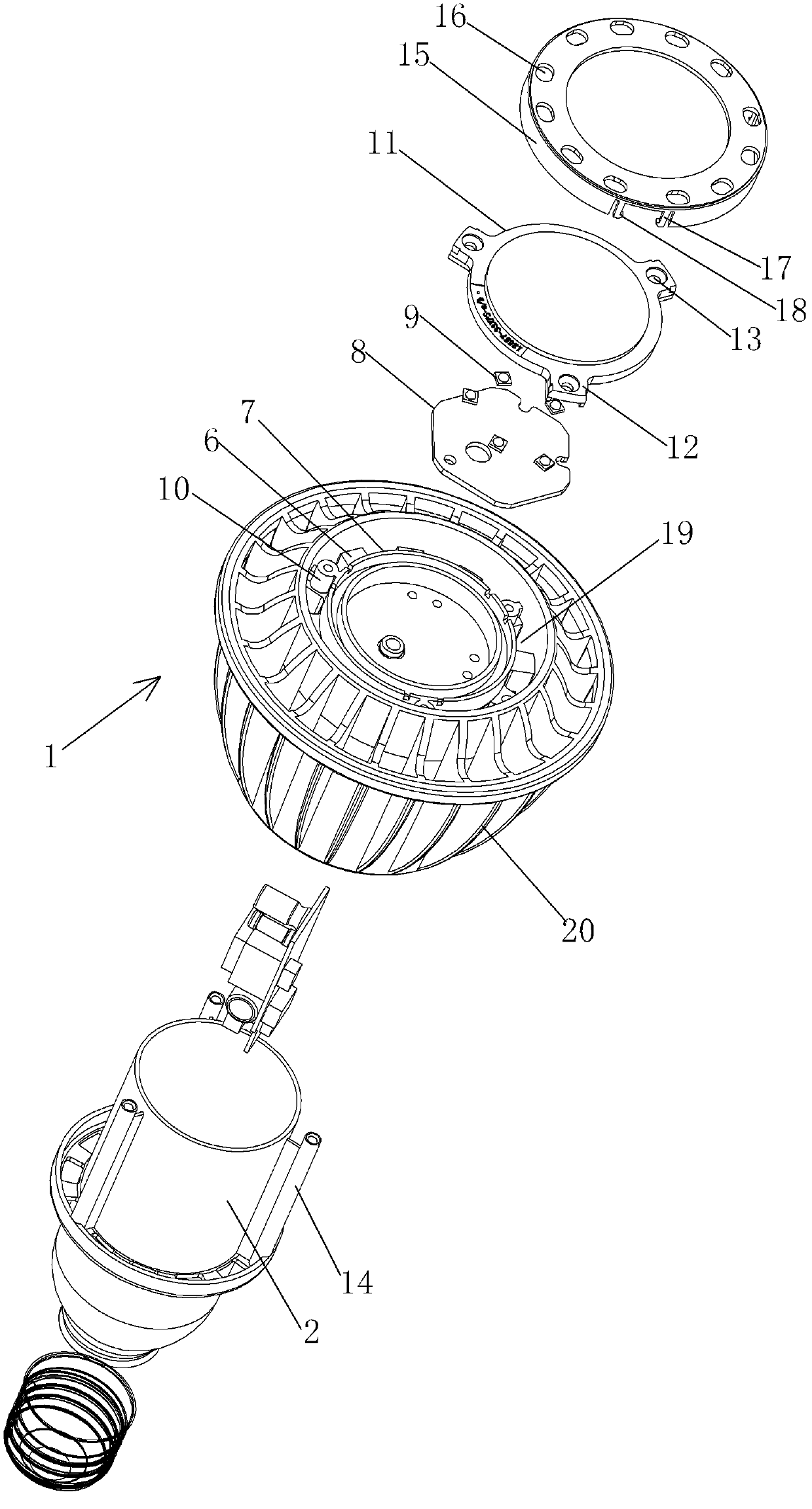
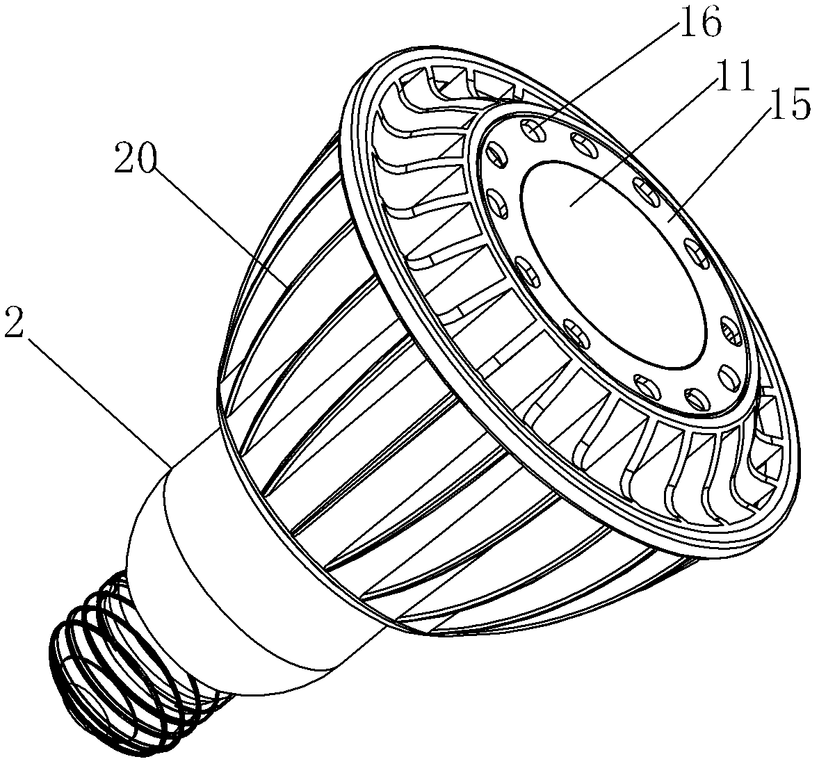
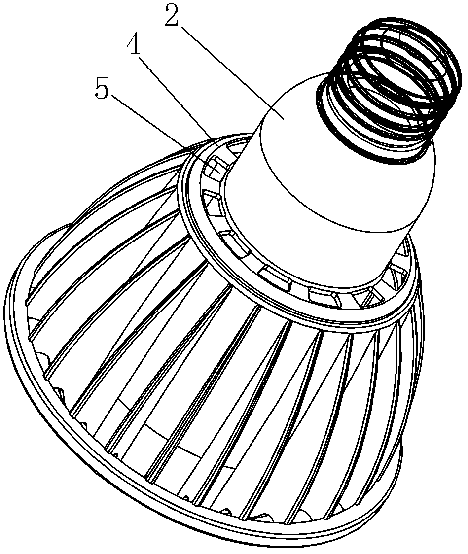
[0022] Embodiment: a kind of LED lamp with good heat dissipation of the present embodiment, such as Figure 1~4 As shown, it includes a heat dissipation lamp cup 1 and a driving power supply housing 2. The interior of the heat dissipation lamp cup 1 is hollow and has openings at both ends. A plurality of heat dissipation fins 20 are distributed on the outer circumference of the heat dissipation lamp cup 1 along the circumferential direction. The cup 1 is nested with the drive power supply housing 2 , and a heat dissipation channel vertically penetrating the openings at both ends of the heat dissipation lamp cup 1 is formed between the drive power supply housing 2 and the heat dissipation lamp cup 1 .

[0023] The heat dissipation channel is formed as follows:

[0024] The outer diameter of the driving power housing 2 is smaller than the inner diameter of the heat dissipation lamp cup 1, and the outer wall of the driving power housing 2 is protruded with a rib 14 for limiting i...


PUM


Abstract

An LED lamp comprises a heat dissipation lamp cup (1) having a hollow inner structure and openings at two ends and comprises a driving power supply housing (2) sleeve-connected to the heat dissipation lamp cup (1). The outer diameter of the driving power supply housing (2) is smaller than the inner diameter of the heat dissipation lamp cup (1). A heat dissipation channel vertically running through the openings at the two ends of the heat dissipation lamp cup (1) is formed between the driving power supply housing (2) and the heat dissipation lamp cup (1). Upper and lower portions of the heat dissipation channel are both in communication with the outside air, so that air can enter the heat dissipation lamp cup (1) and take away the heat generated by a driving power supply, so as to not only prevent the heat dissipation lamp cup (1) from affecting the driving power supply, but also perform effective convectional heat dissipation on the driving power supply, thereby decreasing the rise of the ambient temperature of the power supply by about 5%.

Description

technical field [0001] The invention relates to the technical field of LED lighting, in particular to an LED lamp with good heat dissipation. Background technique [0002] Whether the LED lamp works stably, the quality is good or bad, and the heat dissipation of the lamp itself is very important. In the past, people focused on the heat dissipation of the LED light source, and optimized its heat dissipation performance by improving the shape, structure, and material of the heat dissipation lamp cup, but usually The heat dissipation of the LED drive power supply is not well considered. [0003] For example, the high-power LED lighting lamps in the prior art generally adopt a hollow heat dissipation lamp cup, and a base for fixing the LED light-emitting component is arranged inside the light cup, and the base separates the cavity of the heat dissipation lamp cup into an LED light-emitting component receiving cavity and a drive. The power supply housing cavity, the driving powe...

Claims


Application Information

Patent Timeline
Patent Type & Authority Patents(China)
IPC IPC(8): F21S2/00F21V29/00F21V17/12F21V17/16F21Y101/02
CPCF21V29/2231F21V29/00F21K9/137F21Y2101/02F21K9/233F21V29/773F21Y2115/10
Inventor 梁玉栋陈方沈锦祥
Owner SENGLED OPTOELECTRONICS
Why Eureka
Try Eureka