Chordal gas flowmeter with transducers installed outside the pressure boundary

a flowmeter and transducer technology, applied in the direction of volume/mass flow measurement, measurement devices, instruments, etc., can solve the problems of poor transducer performance, conventional liquid meter housings that do not work in gas environments, and poor signal detection of gas meters at high flowrates, etc., to achieve the effect of safe inspection or replacemen

Active Publication Date: 2013-10-01
SENSIA LLC
View PDF17 Cites 14 Cited by
  • Summary
  • Abstract
  • Description
  • Claims
  • Application Information

AI Technical Summary

Benefits of technology

[0004]The present invention pertains to a flowmeter for measurement of natural gas where accuracy and reliability are essential for custody transfer measurement. The flowmeter measures gas flow rates in a pipe having a channel disposed in the pipe through which natural gas in the pipe flows and plane waves generated by multiple upstream ultrasonic transducers and multiple downstream ultrasonic transducers propagate per plane. The flowmeter defines two crossing planes but may have more or fewer. An important feature of this meter is that the transducer elements can be safely checked or replaced without special tools and without depressurizing the line because of housings which hold the transducer and contain the pipe pressure.

Problems solved by technology

Several problems were solved by using the present invention, they are: depressurizing the pipe gas line or the use of special tools for transducer replacement, poor transducer performance, and poor signal detection for gas meters at high flowrates.
Current gas meters use gas wetted transducers since conventional transducer housings used in liquid meters cannot be used.
Conventional liquid meter housings do not work in a gas environment for two reasons.
First, conventional liquid transducer housings have thick metal windows that cannot transmit sound through gas.
Second, the liquid transducer housings are traditionally welded to the meter body.
This creates noise such that a received signal is poorly detected in a gas meter application.
This may be deadly to the replacer if the tools are improperly handled because the transducer becomes a projectile under pipe gas pressure.
If the gas pipeline has to be depressurized to replace transducers for safety reasons then the pipeline stops and revenue generated by its function is lost.
These transducers suffer from poor bandwidth, poor signal to noise ratio and radial modes in the 100 to 300 kHz frequency range, the preferred operation ultrasonic frequency range for gas meters.
As a result, the received signals can be very distorted and result in poor transit time measurements and poor accuracy of a gas flowmeter at high flow rates >60 feet / second.
Current gas meters also have metal to metal contact between parts even with wetted transducers which cases are made of metal so the flow meter can suffer from poor signal to noise ratio due to acoustic noise of the system.

Method used


Image

  • Chordal gas flowmeter with transducers installed outside the pressure boundary
  • Chordal gas flowmeter with transducers installed outside the pressure boundary
  • Chordal gas flowmeter with transducers installed outside the pressure boundary

Examples


Embodiment Construction

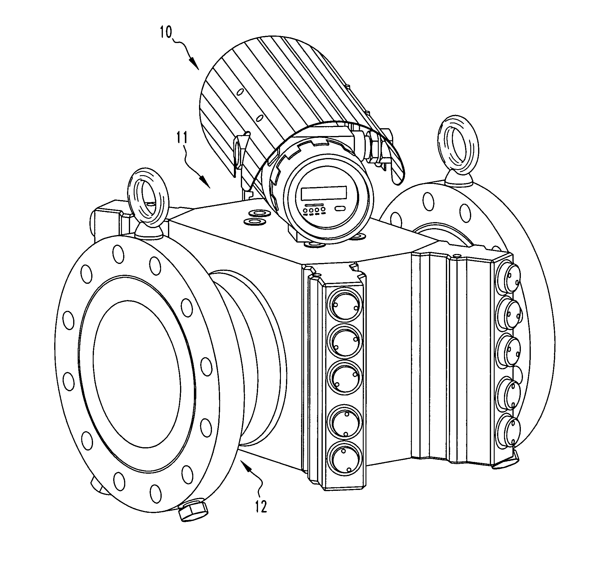
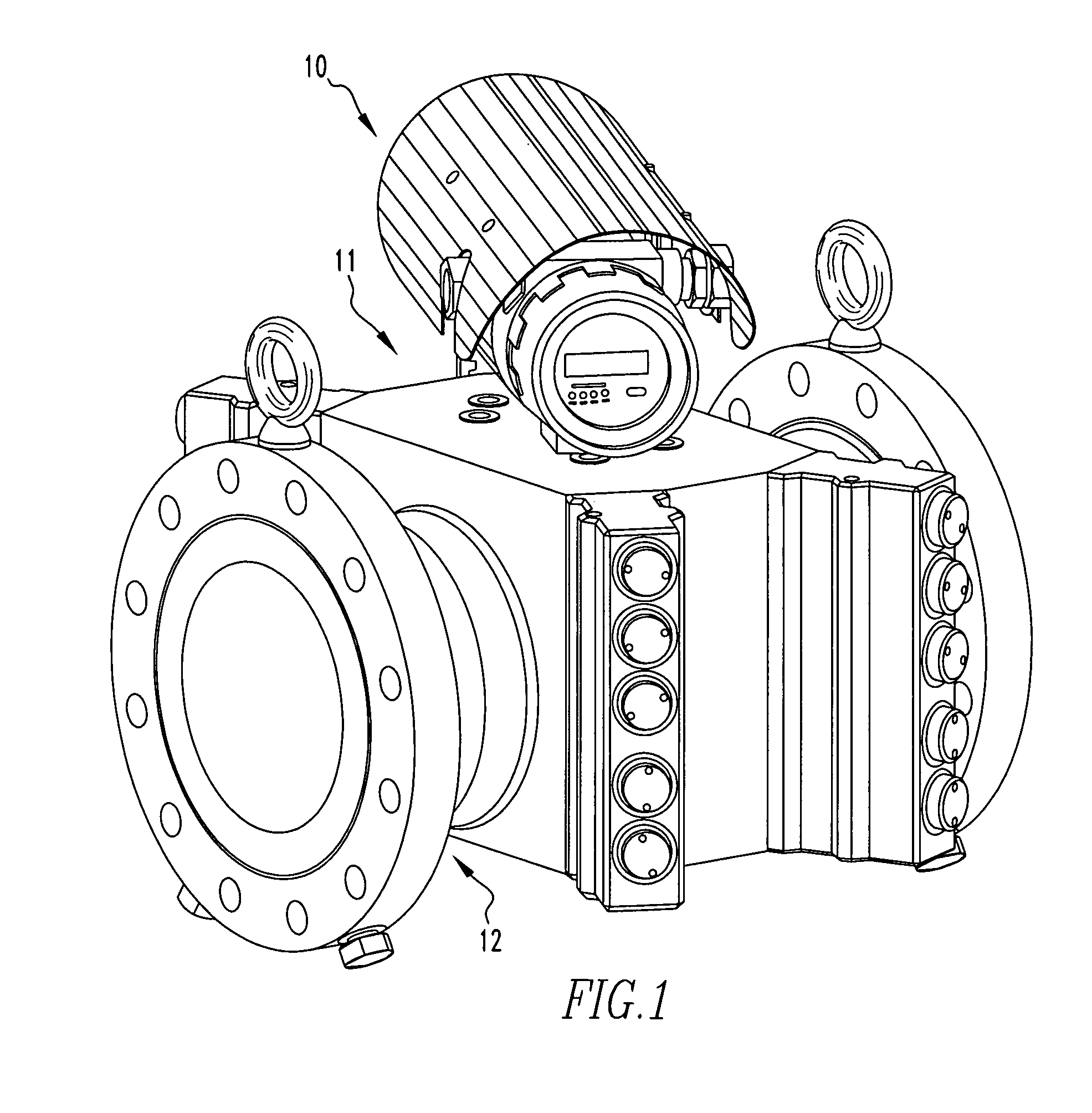
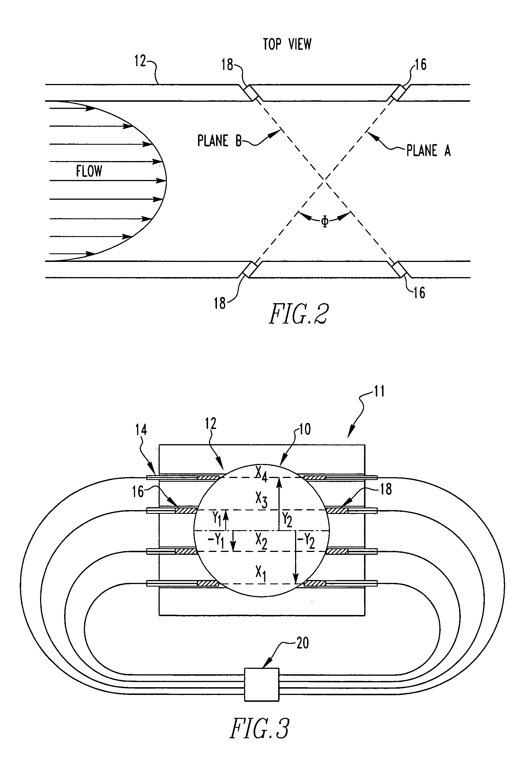
[0015]Referring now to the drawings wherein like reference numerals refer to similar or identical parts throughout the several views, and more specifically to FIGS. 1-3 thereof, there is shown a flowmeter for detecting gas flow rates in a pipe. The flowmeter comprises a container 11 configured to be attached to the pipe having a channel through which the gas flows, and a plurality of recesses. Each recess has a window made of metal that is in acoustic communication with the channel. The flowmeter comprises a plurality of transducers, with one transducer of the plurality of transducers disposed in each recess. The transducers transmit ultrasonic signals into and receiving ultrasonic signals from the channel through the window in the housing recess in which a transducer is disposed. The flowmeter comprises a controller in electrical communication with the plurality of transducers which determines the gas flow rate through the channel from signals received from the transducers.

[0016]Th...


PUM


Abstract

A flowmeter for detecting gas flow rates in a pipe includes a container configured to be attached to the pipe having a channel through which the gas flows, and a plurality of recesses. Each recess has a window made of metal. The flowmeter includes a plurality of transducers, with one transducer of the plurality of transducers disposed in each recess. The flowmeter includes a controller which determines the gas flow rate through the channel.

Description

FIELD OF THE INVENTION[0001]The present invention is related to determining gas flow rates in a pipe with ultrasonic transducers of a flowmeter that send and receive signals into and from the gas flow through a window made of metal that is in acoustic communication with a channel in which the gas flows. (As used herein, references to the “present invention” or “invention” relates to exemplary embodiments and not necessarily to every embodiment encompassed by the appended claims.) More specifically, the present invention is related to determining gas flow rates in a pipe with ultrasonic transducers of a flowmeter that send and receive signals into and from the gas flow through a window made of metal that is in acoustic communication with a channel in which the gas flows where the transducers are disposed in housings that acoustically isolate the transducers so the signal-to-noise ratio of the transducers is improved more than 10 dB.BACKGROUND OF THE INVENTION[0002]This section is int...

Claims


Application Information

Patent Timeline
Patent Type & Authority Patents(United States)
IPC IPC(8): G01F1/66
CPCG01F1/662G01F1/667G01F1/665
Inventor GOTTLIEB, EMANUEL J.AUGENSTEIN, DONALD R.FREUND, JR., WILLIAM R.ZUCKERMAN, RICHARD A.ESTRADA, HERBERTHASTINGS, CALVIN R.
Owner SENSIA LLC
Why Eureka
Try Eureka