Optical interferometer

an interferometer and optical technology, applied in the field of optical interferometers, can solve the problems of low accuracy of high-accurate correction, error of refractive index dispersion in air compositions, etc., and achieve the effect of high-accuracy correction of refractive index

Inactive Publication Date: 2013-11-05
CANON KK
View PDF3 Cites 3 Cited by
  • Summary
  • Abstract
  • Description
  • Claims
  • Application Information

AI Technical Summary

Benefits of technology

[0009]The present invention provides an optical interferometer which is capable of the high accurate correction of the refractive index even when the air composition has the spatial distribution.

Problems solved by technology

However, since the accuracy of the refractive index expression is no more than about 10−8, the method lacks the accuracy for the high-accurate correction, and causes an error of the refractive index dispersion in air compositions in the length measurement environment.

Method used


Image

  • Optical interferometer
  • Optical interferometer
  • Optical interferometer

Examples


embodiment 1

[0019][Embodiment 1]

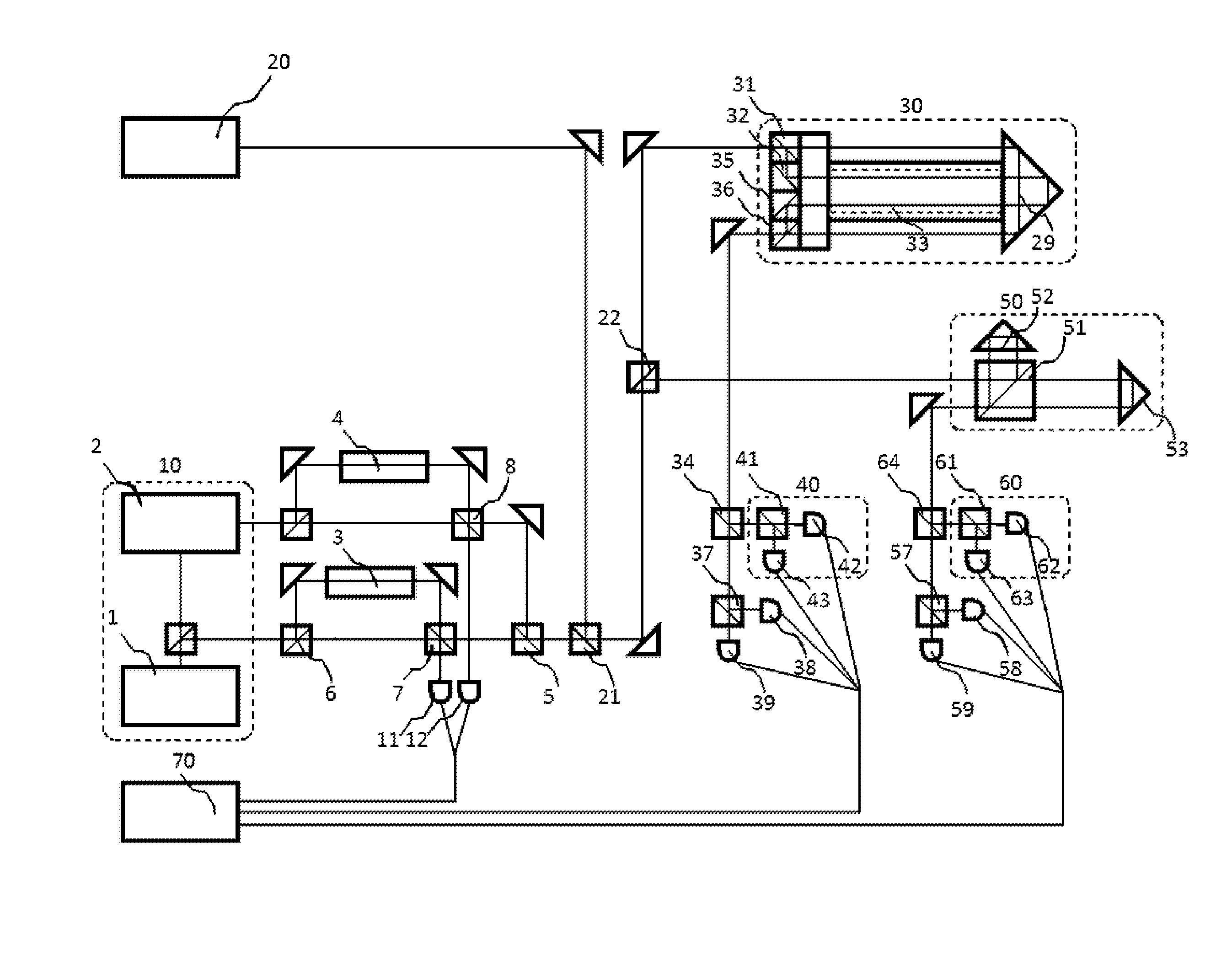
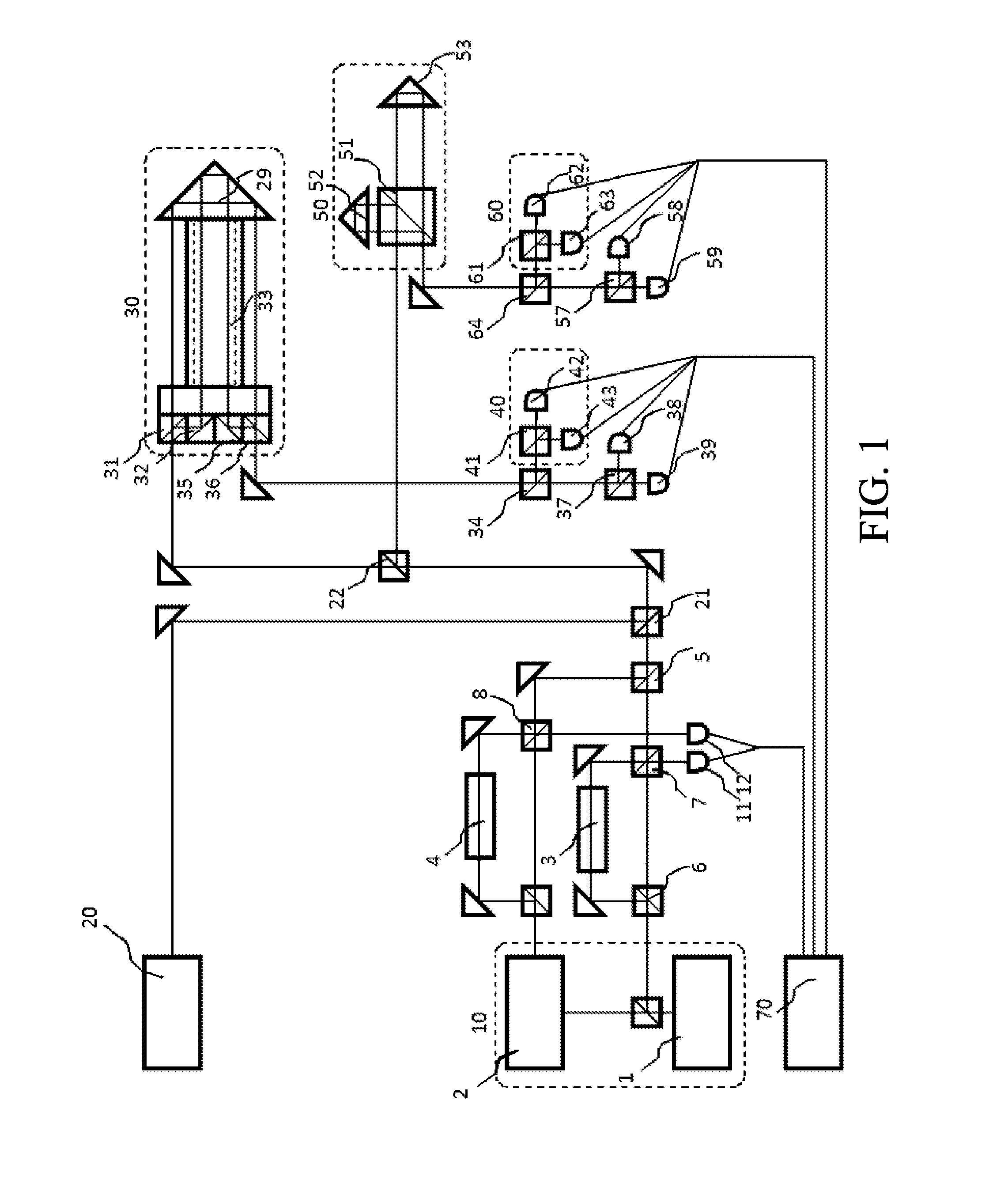
[0020]FIG. 1 is a diagram illustrating a configuration of an interferometer in embodiment 1 of the present invention. An optical interferometer (optical interference measuring apparatus) of embodiment 1 includes a multi-wavelength light source for interference measurement 10, a light source for partial pressure measurement 20, a dispersion measurement interferometer 30, a first partial pressure detector 40, a distance measurement interferometer 50, a second partial pressure detector 60, and an analyzer 70.

[0021]An optical interferometer will be described with reference to FIG. 1 hereinafter.

[0022]A beam (hereinafter referred to as fundamental beam) having a single frequency spectrum and emitted from a light source 1 separates by a non-polarization beam splitter (NPBS), and introduces a part of the beam into a second harmonic generator 2. The second harmonic generator 2 emits a beam (hereinafter referred to as second harmonic beam) having half the wavelength of th...

embodiment 2

[0085][Embodiment 2]

[0086]Next, embodiment 2 of the present invention is described with reference to FIG. 4. FIG. 4 is a diagram illustrating an apparatus configuration in embodiment 2 of the present invention.

[0087]In embodiment 2, a wavelength scanning light source 110 is added to the multi-wavelength light source 100, and detectors 120, 130 and 140 for detecting the optical path length of the wavelength of the wavelength scanning light source 110 are added, and thereby directly measuring the absolute optical path length including the order of interference.

[0088]Details will be described with reference to FIG. 4 hereinafter.

[0089]A beam emitted from the wavelength scanning light source 110 is split into two by a NPBS 113, and one enters a frequency shift unit 111. In what follows, a beam which transmits the frequency shift unit 111 is called “frequency shifted wavelength scanning beam (wavelength scanning frequency shift light flux)”, and the other is called “wavelength scanning b...


PUM


Abstract

An optical interferometer including, an analyzer configured to calculate an air dispersion ratio of air in the dispersion measurement interferometer excluding the component gas on the basis of a detection result of a first partial pressure detector, to calculate dispersion of air in a distance measurement interferometer from the calculated air dispersion ratio and a detection result of a second partial pressure detector, and to calculate a geometrical distance of the optical path length difference between a reference surface and a target surface.

Description

BACKGROUND OF THE INVENTION[0001]1. Field of the Invention[0002]The present invention relates to an optical interferometer to measure a distance and a position of a target.[0003]2. Description of the Related Art[0004]Conventionally, the method of measuring the distance by the optical interferometer is well-known. A distance measurement by the optical interferometer uses a signal of interference light (interference signal) generated by an interference between a reference beam which is reflected on a reference surface being the distance measurement reference and a test beam which is reflected on a target surface attached to a target, and thereby using a wavelength of the light as the scale. Since the wavelength changes by a refractive index of an optical path of the test beam, a high-accurate correction of the refractive index is essential in order to achieve a high-accurate length measurement in an atmosphere.[0005]Japanese Patent Laid-Open No. H10-281717 discloses a method of correc...

Claims


Application Information

Patent Timeline
Patent Type & Authority Patents(United States)
IPC IPC(8): G01B9/02
CPCG01B9/02007G01B9/0207G01B9/02027G01B2290/60G01B2290/45
Inventor KURAMOTO, YOSHIYUKISASAKI, TAKAMASA
Owner CANON KK
Why Eureka
Try Eureka