System, method, and computer program product for servo compensator switching in high vibration environments

a technology of servo compensator and high vibration environment, applied in the direction of maintaining head carrier alignment, recording signal processing, instruments, etc., can solve the problems of vibration environment operation problems of enhanced servo compensators, and achieve the effect of reducing the determined skew error and reducing the determined position error

Inactive Publication Date: 2013-12-17
INT BUSINESS MASCH CORP
View PDF14 Cites 2 Cited by
  • Summary
  • Abstract
  • Description
  • Claims
  • Application Information

AI Technical Summary

Benefits of technology

[0005]A method according to one embodiment includes sensing a servo sensor while a longitudinal tape is moved past a magnetic head, wherein the servo sensor is configured for sensing a lateral position of the magnetic head with respect to at least one defined servo track of the longitudinal tape; determining position error between the magnetic head and a desired position related to the at least one defined servo track; providing signals to operate a fine actuator to translate the magnetic head laterally in a manner to reduce the determined position error, wherein the fine actuator is configured to translate the magnetic head laterally with respect to the longitudinal tape; determining skew error between an angle of the magnetic head relative to tape motion and a desired angle relative to the at least one defined servo track; providing signals to operate a skew actuator to translate the magnetic head rotationally in a manner to reduce the determined skew error, wherein the skew actuator is configured to translate the magnetic head rotationally with respect to the longitudinal tape; determining when the position error is greater than a position error threshold; determining when the skew error is greater than a skew error threshold; and transitioning the fine actuator from a normal compensation mode to a high energy compensation mode when the position error is greater than the position error threshold for a first predetermined period and the skew error is greater than the skew error threshold for a second predetermined period.

Problems solved by technology

However, the enhanced servo compensator has problems operating in vibration environments because the external vibrations tend to push the head off track while operating the tape drive.

Method used


Image

  • System, method, and computer program product for servo compensator switching in high vibration environments
  • System, method, and computer program product for servo compensator switching in high vibration environments
  • System, method, and computer program product for servo compensator switching in high vibration environments

Examples


Embodiment Construction

[0017]The following description is made for the purpose of illustrating the general principles of the present invention and is not meant to limit the inventive concepts claimed herein. Further, particular features described herein can be used in combination with other described features in each of the various possible combinations and permutations.

[0018]Unless otherwise specifically defined herein, all terms are to be given their broadest possible interpretation including meanings implied from the specification as well as meanings understood by those skilled in the art and / or as defined in dictionaries, treatises, etc.

[0019]It must also be noted that, as used in the specification and the appended claims, the singular forms “a,”“an” and “the” include plural referents unless otherwise specified.

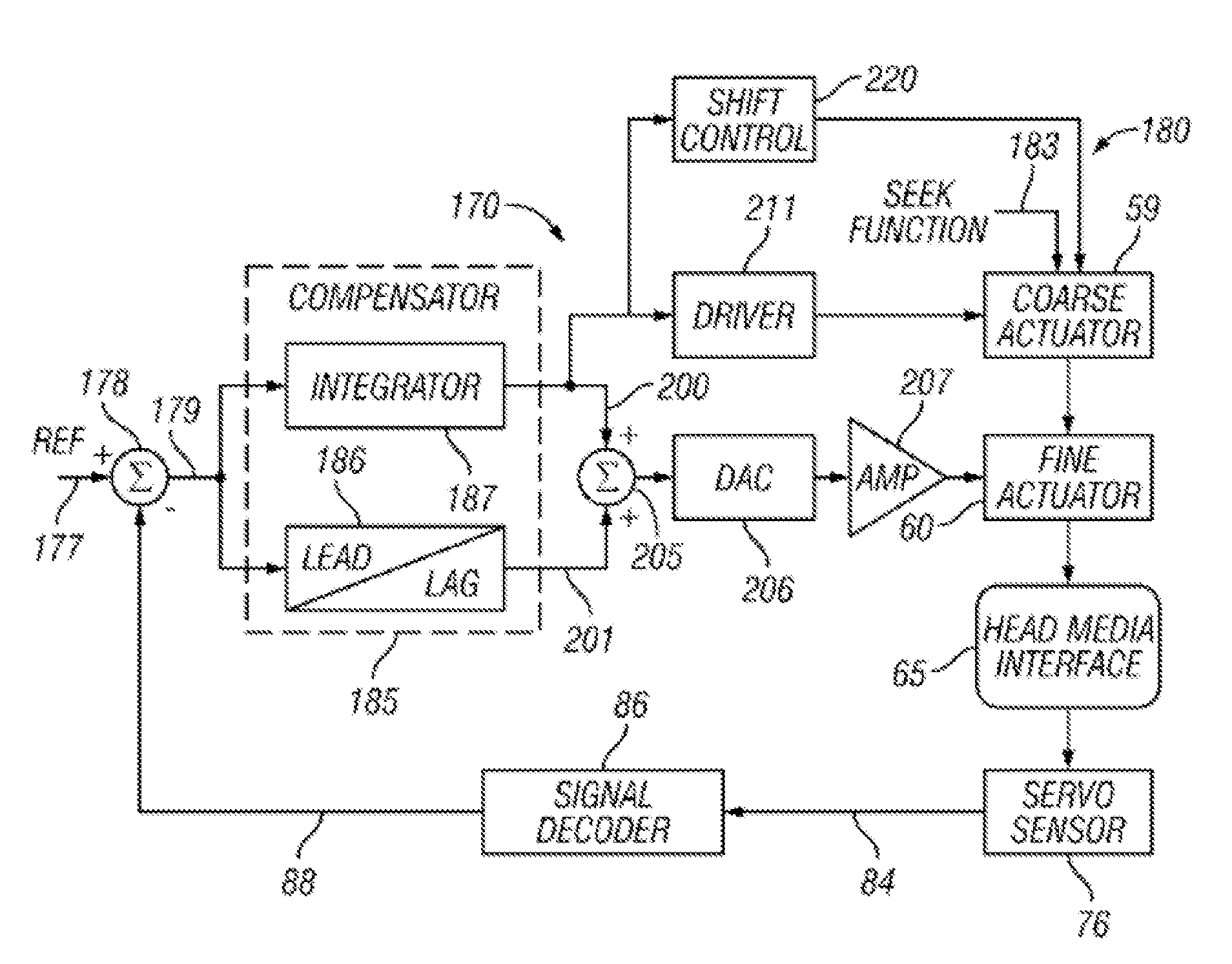
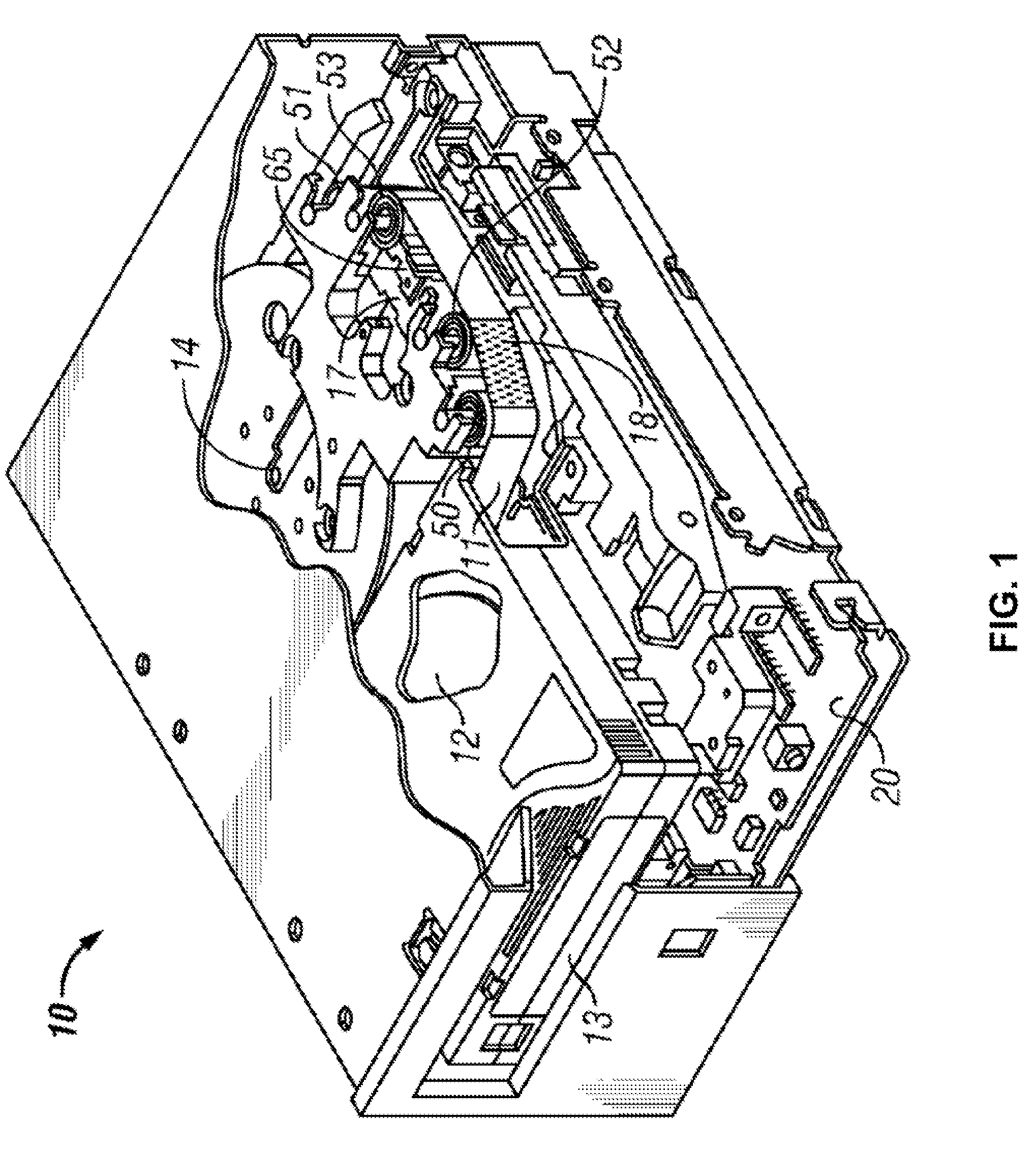
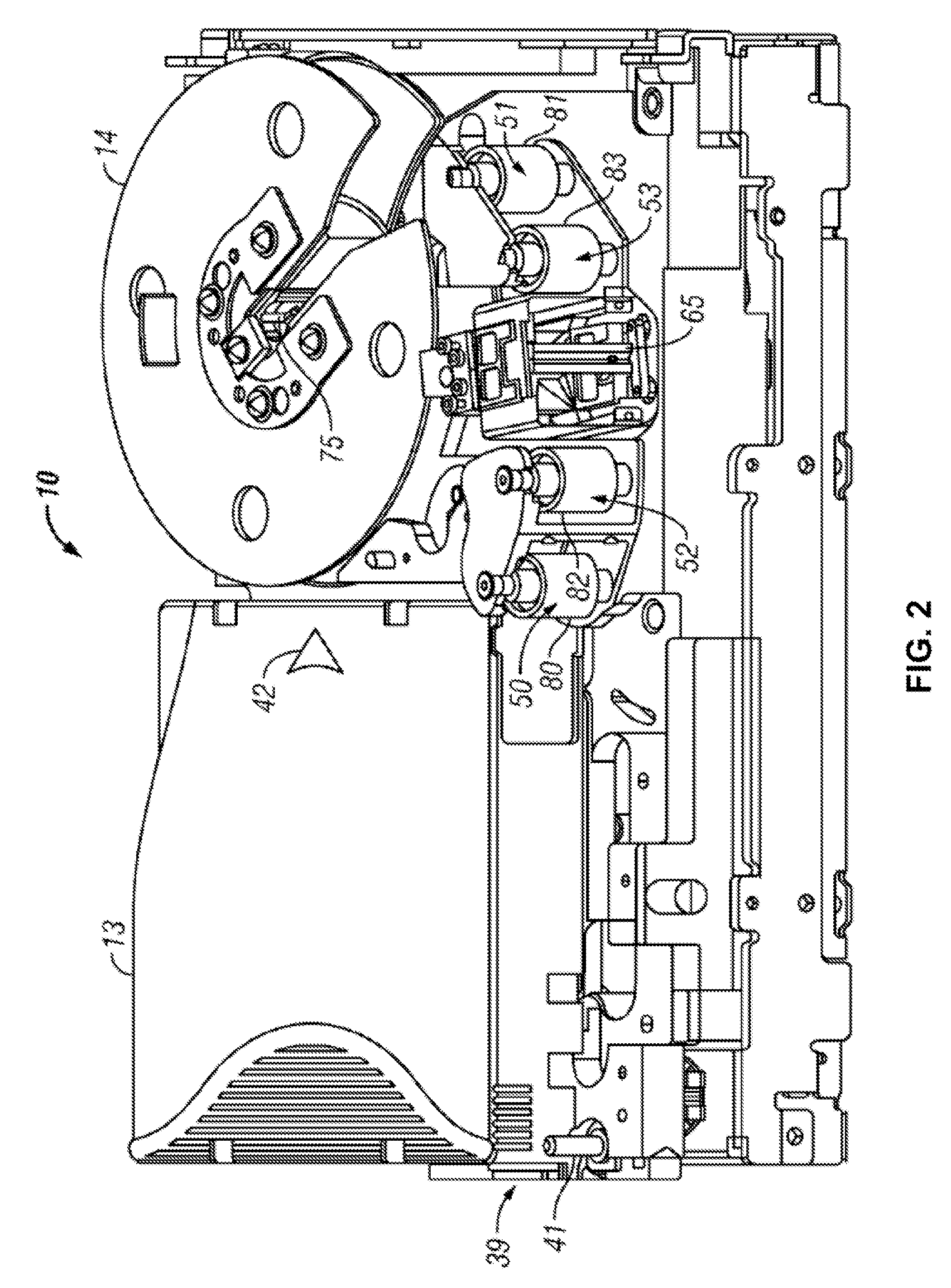
[0020]The following description describes methods and systems for accounting for vibrations that effect track-following a servo track when operating a tape drive.

[0021]In one general embodiment...


PUM

PropertyMeasurementUnit
threshold erroraaaaaaaaaa

Abstract

A tape drive system according to one embodiment includes a magnetic head having at least one servo sensor; a tape motion controller; a fine actuator; a skew actuator; a coarse actuator; and a control. The control is configured to perform various operations that help account for vibrations that effect track-following a servo track when operating a tape drive. Additional systems, methods and computer program products are also described.

Description

BACKGROUND[0001]The present invention relates to track-following a servo track in a longitudinal tape system, and more particularly, to track-following a servo track in high vibration environments.[0002]Current longitudinal tape drives, such as IBM® LTO Generation 5 tape drives, IBM® 3592E07 tape drives and later among others, have methods to track-follow a servo track. The track-following is performed by monitoring a position error signal (PES) which is produced by comparing a desired position to an actual position of the magnetic head over the tape.[0003]As new tape drives and tape media are developed, track density of the tape media increases to provide more capacity using the same tape width. In order to accomplish this, track widths have become narrower. When these tape media are used, the track following servo of the tape drive has to perform better to properly follow the narrower track width. To achieve this, in conventional systems, the track following servo compensator is e...

Claims


Application Information

Patent Timeline
Patent Type & Authority Patents(United States)
IPC IPC(8): G11B5/584G11B15/04G11B5/00
CPCG11B5/584G11B15/32
Inventor BUI, NHAN X.HANCOCK, REED A.TAKETOMI, TOMOKO
Owner INT BUSINESS MASCH CORP
Why Eureka
Try Eureka