System and method for fast center calibration of a tape drive for a flangeless tape path

a tape drive and flangeless technology, applied in the field of servo systems for trackfollowing longitudinal tape movement, can solve the problems of coarse actuator wear and shorten the life of coarse actuators, unsatisfactory dynamic effects, and fine actuators that are not able to drive the head to the other side of longitudinal tapes, so as to reduce the determined position error

Inactive Publication Date: 2012-12-06
IBM CORP
View PDF10 Cites 5 Cited by
  • Summary
  • Abstract
  • Description
  • Claims
  • Application Information

AI Technical Summary

Benefits of technology

[0012]A method according to another embodiment includes sensing a first servo sensor while a longitudinal tape is moved in a first direction, wherein the first servo sensor is configured for sensing a lateral position of a magnetic head with respect to at least one defined servo track of the longitudinal tape; determining position error between the magnetic head and a desired position related to the at least one defined servo track; providing signals to operate a fine actuator to translate the magnetic head laterally in a manner to reduce the determined position error, wherein the fine actuator is configured to translate the magnetic head laterally with respect to the longitudinal tape; calculating a first avera

Problems solved by technology

The flanges of the tape guides, such as rollers, limit the lateral motion of the tape, but may tend to flex the tape and to introduce debris accumulation of the flanges that impact the lifetime of the tape and in addition create undesirable dynamic effects.
This motion tends to wear and shorten the life of the coarse actuator, and is a use of power by the coarse actuator.
Therefore, if the head is positioned near a top or bottom of the longitudinal tape before fine actuation is performed, there is a chance that the fine actuator may not be able to drive the head to the other side of the longitudinal tape.
Finding the midpoint of the lateral tape excursion is not easy, as the midpoint of the lateral tape excursion is unique to each drive and the coarse and fine actuator systems have no absolute reference positions relative to the longitudinal tape path.
However, some tapes behave in ways that make it difficult to find these extremes from which the midpoint of the lateral

Method used


Image

  • System and method for fast center calibration of a tape drive for a flangeless tape path
  • System and method for fast center calibration of a tape drive for a flangeless tape path
  • System and method for fast center calibration of a tape drive for a flangeless tape path

Examples


Embodiment Construction

[0024]The following description is made for the purpose of illustrating the general principles of the present invention and is not meant to limit the inventive concepts claimed herein. Further, particular features described herein can be used in combination with other described features in each of the various possible combinations and permutations.

[0025]Unless otherwise specifically defined herein, all terms are to be given their broadest possible interpretation including meanings implied from the specification as well as meanings understood by those skilled in the art and / or as defined in dictionaries, treatises, etc.

[0026]It must also be noted that, as used in the specification and the appended claims, the singular forms “a,”“an” and “the” include plural referents unless otherwise specified.

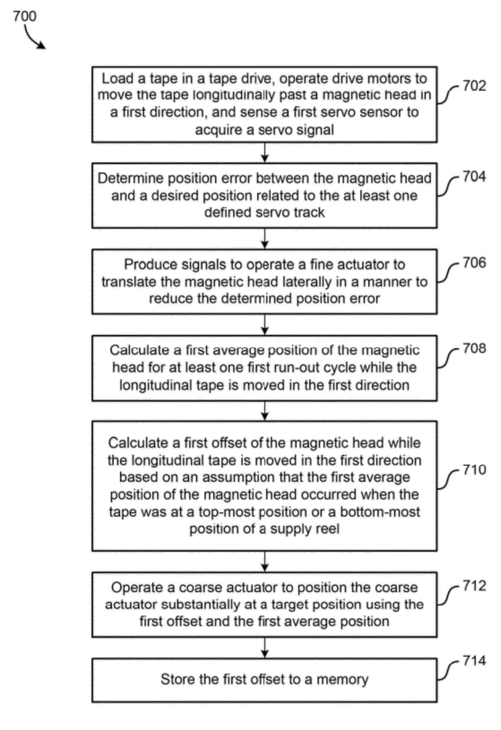
[0027]The following description describes methods and systems for estimating a midpoint of lateral tape excursion of a flangeless tape path for calibrating a tape drive.

[0028]In one general emb...


PUM


Abstract

A servo system according to one embodiment includes at least one servo sensor for sensing a lateral position of a magnetic head with respect to at least one defined servo track of a longitudinal tape; a fine actuator configured to translate the magnetic head laterally with respect to the longitudinal tape; a coarse actuator configured to translate the fine actuator laterally with respect to the longitudinal tape; and a servo control. The servo control is configured to perform various operations that may be used to estimate a midpoint of lateral tape excursion of a flangeless tape path for calibrating a tape drive. Additional systems are also presented.

Description

BACKGROUND[0001]The present invention relates to servo systems for track-following longitudinal tape movement in a longitudinal direction, and more particularly, to fast center calibration of a tape drive that is used with a flangeless tape path.[0002]The function of a servo system for longitudinal tape, such as magnetic tape, is to move a head laterally in respect to the longitudinal tape to accurately follow the lateral movement of the tape, for example, during read / write operations of the head. If done accurately, the data tracks are written and read in straight lines along the longitudinal tape as the tape is moved in the longitudinal direction. With respect to magnetic tape, the data comprises parallel stripes in the longitudinal direction of the magnetic tape. Servo tracks are prerecorded in the magnetic tape parallel to, and offset from, the expected data stripes. Typically, the lateral movement of the magnetic tape is constrained by flanges present on tape guides at either s...

Claims


Application Information

Patent Timeline
IPC IPC(8): G11B5/584
CPCG11B21/103G11B5/584
Inventor BUI, NHAN X.HANCOCK, REED A.INCH, RANDY C.
Owner IBM CORP
Why Eureka
Try Eureka