
Multi-component display and merchandise systems

a multi-component, merchandise technology, applied in the field of merchandise display, pushing, and dividing systems, can solve the problems of reducing the effectiveness of the system, reducing the efficiency of the system, and difficult or impossible to install pusher systems with significant height dividers, so as to achieve smooth pushing and less binding

Active Publication Date: 2014-01-14
RTC IND
View PDF321 Cites 39 Cited by
  • Summary
  • Abstract
  • Description
  • Claims
  • Application Information

AI Technical Summary

Benefits of technology

This patent describes a system for displaying and pushing merchandise on a shelf. The system includes a base, a divider, and a pusher mechanism. A track is included in the base and a pusher can be connected to the track to move the merchandise to the front of the shelf. The pusher has an offset portion that allows for smoother pushing and less binding when displaying wide products. The system can also have engagement mechanisms to keep the components in place and a unique pusher mechanism with an extendable pusher face that enhances the pushing leverage on the merchandise. Overall, the system provides a more efficient and effective way to display and push merchandise on a shelf.

Problems solved by technology

However, many freezers, like some other shelving areas in retail environments, can have a limited height between shelves and it can be difficult or impossible to install pusher systems with dividers of significant height in such environments.
While a divider of a lesser height may be acceptable for some environments and for some products, for others, such as bagged frozen foods in a grocer freezer, a lesser height divider is less acceptable.
When a display system utilizing a pusher is employed on bagged frozen foods, for example, the products may move laterally over a divider and reduce the effectiveness of the system if the divider is of a lesser height.
The bags may be forced by the pusher between the divider and the upper shelf or top wall of the freezer unit, impeding the pusher from advancing additional product to the front of the display.
With a divider of a lesser height, the system may not operate efficiently.

Method used


Image

  • Multi-component display and merchandise systems
  • Multi-component display and merchandise systems
  • Multi-component display and merchandise systems

Examples


example

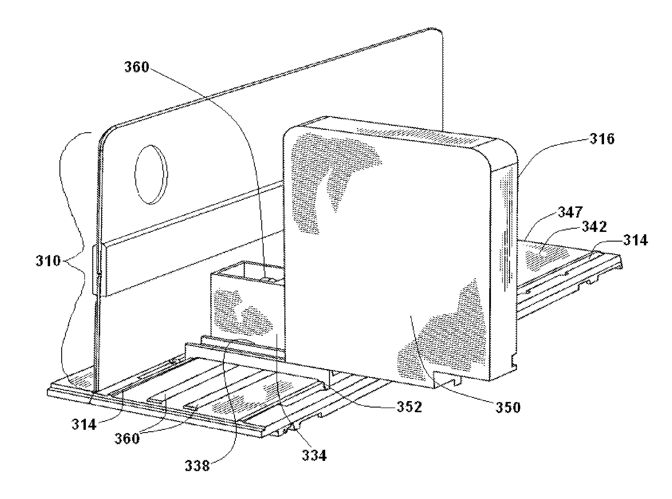
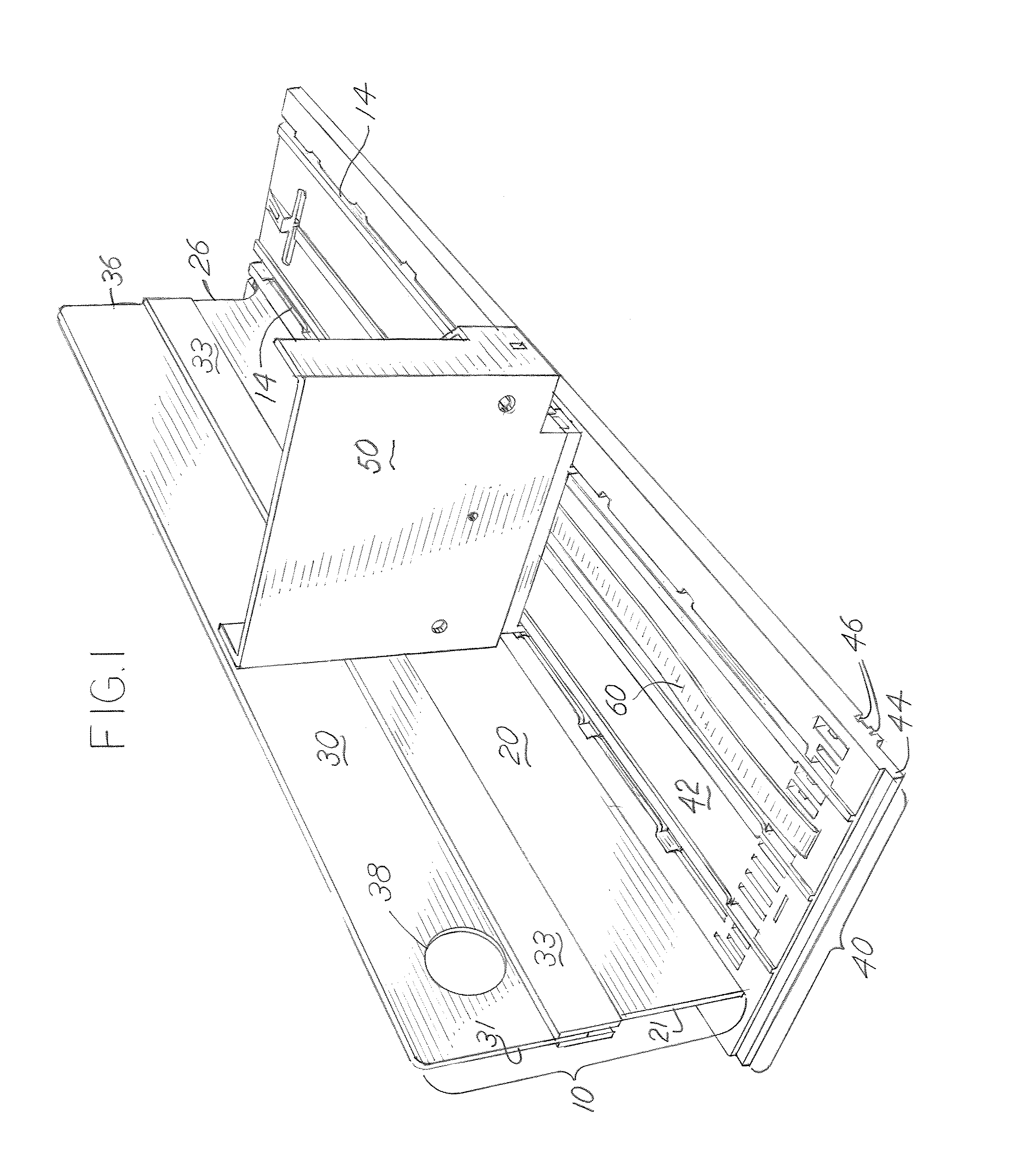
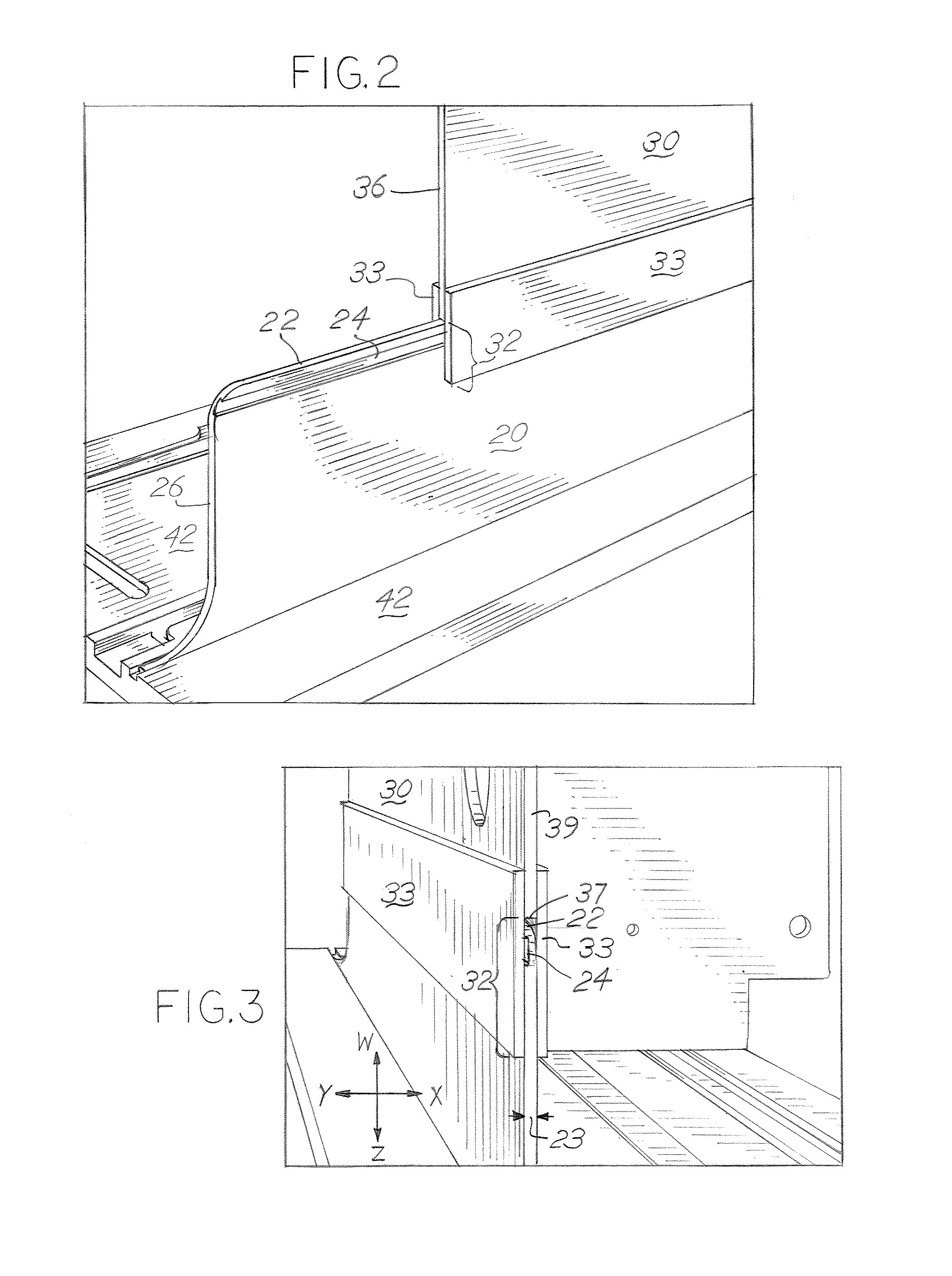
[0092]A divider for dividing displayed merchandise into rows comprises a base connected to a shelf. The base includes at least one track to which a pusher is operatively connected. The pusher has the ability to move along the track and the pusher includes a pusher base and a pusher face mounted to the pusher base. The divider includes a lower divider component and an upper divider component. The lower divider component extends outward from the base and the lower component has a groove located below and parallel to at least a portion of the upper edge of the lower component. The upper component has a flange that slidably engages the groove of the lower component. The groove and flange are positioned to restrict the movement of the upper component when the front ends of the upper component and lower component are in substantial alignment. An aperture is located in the upper component to facilitate the installation and removal of the upper component.


PUM


Abstract

A multi-component divider including a first divider component and a connection mechanism for a second divider component. The second divider component connects to the first divider component when the first divider component is connected to a base. The second divider component extends above the first divider component, thereby extending the overall height of the divider. The base and multi-component divider can be used in locations where there is limited space between shelves, such as a shelf in a freezer or refrigerated display, or in any application where a higher divider may be preferred, but cannot be installed. The base can additionally include a pusher moveable along a longitudinal direction of the base, wherein the pusher is also adjustable linearly along a direction perpendicular to the longitudinal direction of the base.

Description

CROSS REFERENCE TO RELATED APPLICATIONS[0001]This application is a continuation in part of U.S. application Ser. No. 11 / 465,936, filed Aug. 21, 2006, which issued as U.S. Pat. No. 7,891,503, which is a continuation of U.S. application Ser. No. 11 / 216,493, filed Aug. 31, 2005, and issued as U.S. Pat. No. 7,093,546, which is a continuation of U.S. application Ser. No. 10 / 474,490 filed Oct. 8, 2003, and issued as U.S. Pat. No. 6,964,235, which claims priority to U.S. Provisional Application Ser. No. 60 / 291,732, filed May 17, 2001, and PCT Application Ser. No. PCT / US02 / 15760, filed May 17, 2002; this application also is a continuation in part of U.S. application Ser. No. 10 / 772,134, filed Feb. 3, 2004, which issued as U.S. Pat. No. 7,152,536; this application claims priority to U.S. provisional Application Ser. No. 60 / 780,971, filed Mar. 10, 2006 and each of the applications mentioned above.[0002]U.S. Pat. No. 6,964,235 and U.S. patent application Ser. Nos. 10 / 772,134 and 11 / 216,493, ar...

Claims


Application Information

Patent Timeline
Patent Type & Authority Patents(United States)
IPC IPC(8): A47F1/04
CPCA47F5/005A47F1/126A47F1/04A47F1/125
Inventor HARDY, STEPHEN, N.
Owner RTC IND
Learn More