Mat and carrier for an object

Inactive Publication Date: 2014-02-04
ROSA NOEL
View PDF27 Cites 26 Cited by
  • Summary
  • Abstract
  • Description
  • Claims
  • Application Information

AI Technical Summary

Benefits of technology

[0026]In another embodiment of the invention carrier transports the electrical pedal mat. The electrical pedal mat engages an electrical pedal component. The carrier and electrical pedal mat comprise a case having a body and closure wall pivotably mounted to the body. The body defines a case chamber. An insert panel is removably secured within the case chamber. The insert panel defines a first case chamber and a second case chamber within the body. The insert panel is positioned within the sheet channel for positioning the first sheet side within the first case chamber and the second sheet side within the second case chamber. The first case chamber and the second case chamber housing and protecting the electrical pedal component.
[0027]In another embodiment of the invention, a receptacle receives an object. The surface supports the receptacle. The receptacle comprises a flexible sheet defining a top surface, a bottom surface and an outer edge. The flexible sheet has a first sheet half and a second sheet half coupled by a crease area. A top hook and loop layer is coupled to the top surface of the flexible sheet. The object hook and loop layer is coupled to the object. The top hook and loop layer and the object hook and loop layer interlock for coupling the object to the flexible sheet. A carrier defines an exterior surface, an interior surface and an outer rim. The carrier has a first carrier panel and a second carrier panel coupled by a carrier spine. A first sheet hook and loop layer is coupled to the bottom surface and the first sheet half of the flexible sheet. A carrier hook and loop layer is coupled to the interior surface and the first carrier panel of the carrier. The first sheet hook and loop layer is removably coupling with the carrier hook and loop layer for defin

Problems solved by technology

Transporting these devices without loss or damage became a problem for the musician.
Additionally, the time required to organize and assemble the effects boxes and their associated wiring and power supplies became a set-up problem.
None, however completely satisfies the requirements for a complete solution to the aforestated problem.
It is comprised of a combination of components that a

Method used


Image

  • Mat and carrier for an object
  • Mat and carrier for an object
  • Mat and carrier for an object

Examples


Embodiment Construction

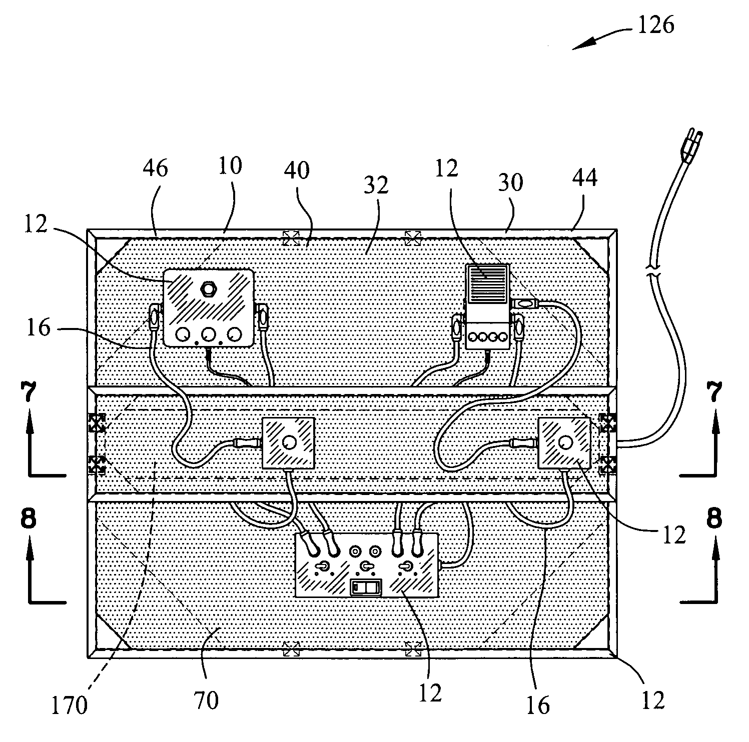
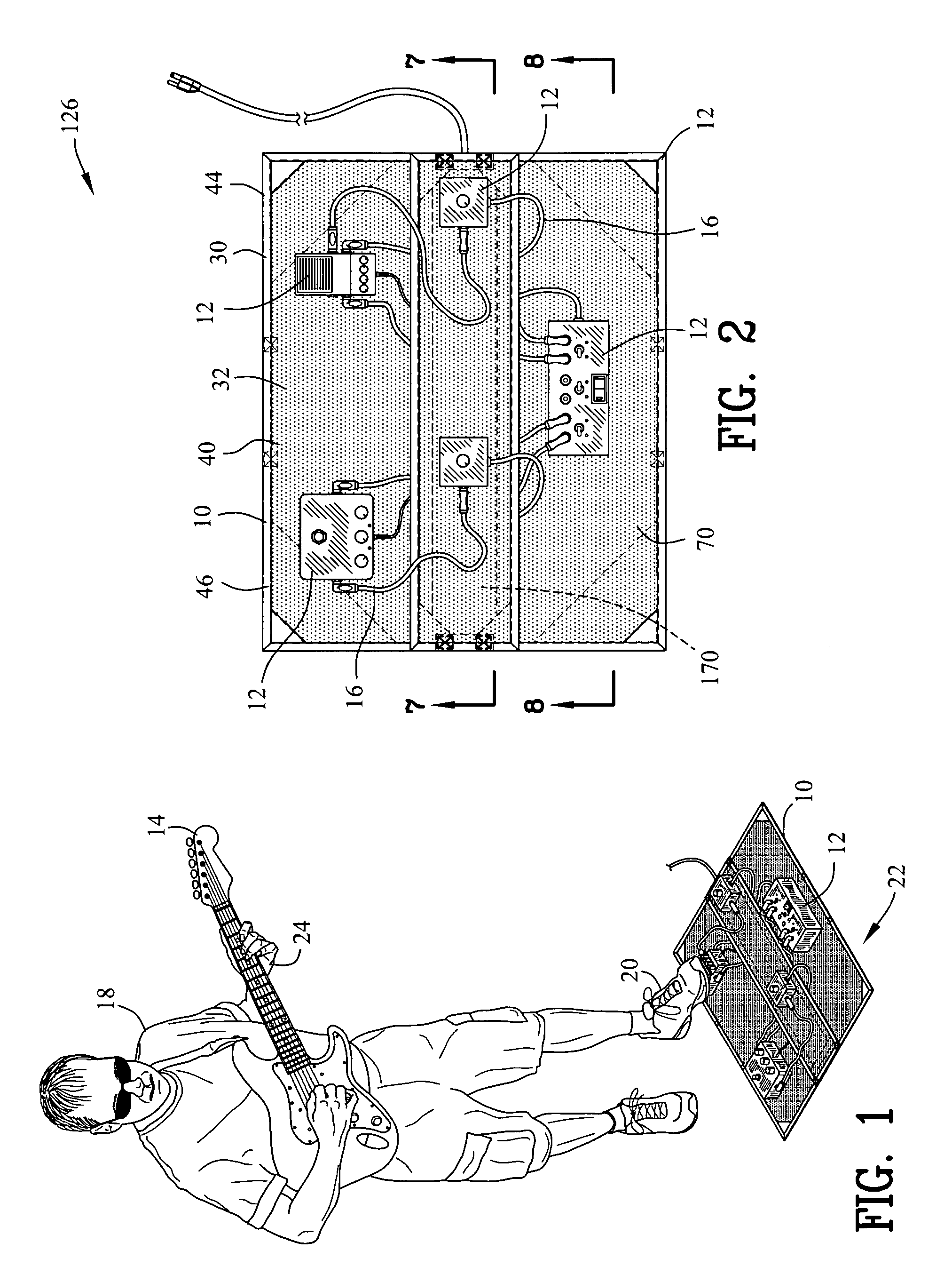
[0063]FIGS. 1-8 are various views of a mat or electrical pedal mat 10 for engaging an object or electrical pedal component 12. The electrical pedal component 12 is electrically coupled to a musical instrument 14 by an electrical conduit 16. An individual 18 may operate the electrical pedal component 12 by depressing the electrical pedal component 12 by a foot 20 of the individual 18. A surface 22 supports the electrical pedal mat 10.

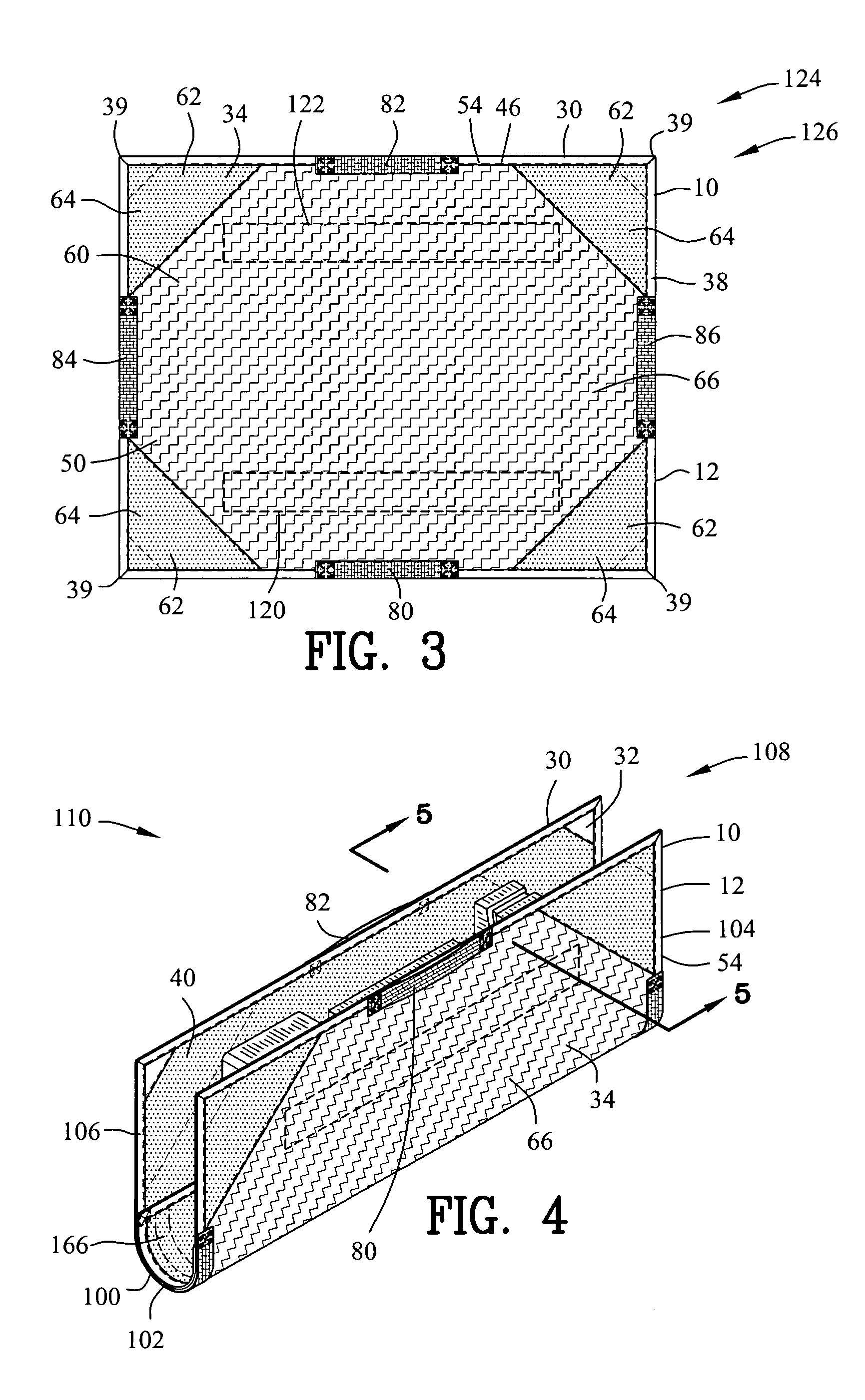
[0064]The electrical pedal mat 10 includes a flexible sheet 30 defining an upper flexible sheet 32 and a lower flexible sheet 34. The flexible sheet 30 may be constructed of a woven polymeric material or other suitable materials. The upper flexible sheet 32 has a top surface 40, a bottom surface 42 and an outer edge 44. Similarly, the lower flexible sheet 34 has a top surface 50, a bottom surface 52 and an outer edge 54. The flexible sheet 30 is shown as a rectangle 38 including four right angles 39 however the flexible sheet 30 may also include various ...


PUM


Abstract

A mat is disclosed for engaging an object. A surface supports the mat. The mat comprises a flexible sheet defining a top surface, a bottom surface and an outer edge. A gripper layer is coupled to the bottom surface for resisting displacement of the flexible sheet relative to the surface. A top hook and loop layer is coupled to the top surface of the flexible sheet. An object hook and loop layer is coupled to the object. The top hook and loop layer and the object hook and loop layer interlock for coupling the object to the flexible sheet.

Description

CROSS-REFERENCE TO RELATED APPLICATIONS[0001]This application claims benefit of U.S. Patent Provisional application Ser. No. 61 / 284,815 filed Dec. 23, 2009. All subject matter set forth in provisional application Ser. No. 61 / 284,815 is hereby incorporated by reference into the present application as if fully set forth herein.BACKGROUND OF THE INVENTION[0002]1. Field of the Invention[0003]This invention relates to mats and more particularly to an electrical pedal mat and carrier for engaging an electrical pedal component.[0004]2. Background of the Invention[0005]Following the invention of the solid body electric guitar in the mid 1940's, consistent improvements and innovations have been made to the instrument and it's support accessories. Eventually, the development of electric base guitars followed. Starting in the 1960's, musicians began experimenting with various sound and tone modulating devices designed to create various effects. Typically, these effects or so called “stomp boxe...

Claims


Application Information

Patent Timeline
IPC IPC(8): G10D9/00
CPCG10D9/00G10G7/005A47G27/0212G10H1/32G10H1/348G10H2230/371H02G3/34
Inventor ROSA, NOEL
Owner ROSA NOEL
Why Eureka
Try Eureka