Heater and image heating apparatus having the heater installed therein

a heating apparatus and heater technology, applied in the direction of heater elements, instruments, electrographic processes, etc., can solve the problems of difficult to set the total resistance of the heat generation resistor in one heater to fall within the range for use at commercial power, and damage to each part of the apparatus, so as to prevent heat generation distribution

Inactive Publication Date: 2014-02-04
CANON KK
View PDF16 Cites 16 Cited by
  • Summary
  • Abstract
  • Description
  • Claims
  • Application Information

AI Technical Summary

Benefits of technology

[0008]According to the present invention, the heat generation distribution is prevented from becoming non-uniform in the longitudinal direction of the heater.

Problems solved by technology

If the temperature in the non-sheet feeding portion is increased to be too high, each part in the apparatus may be damaged.
However, a material having PTC is significantly low in volume resistance, and hence it is extraordinary difficult to set the total resistance of the heat generation resistors in one heater to fall within a range for use at commercial power.

Method used


Image

  • Heater and image heating apparatus having the heater installed therein
  • Heater and image heating apparatus having the heater installed therein
  • Heater and image heating apparatus having the heater installed therein

Examples


first embodiment

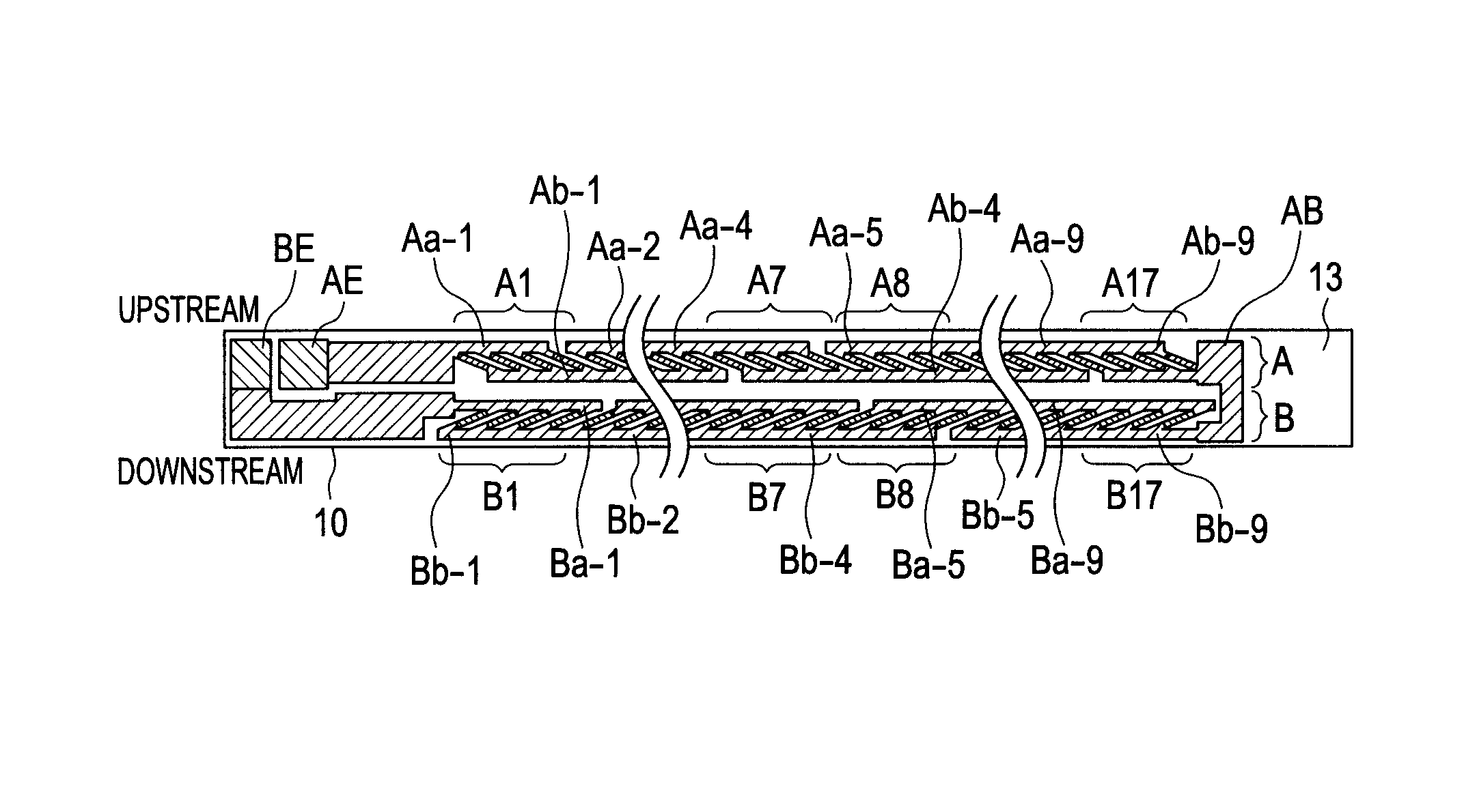
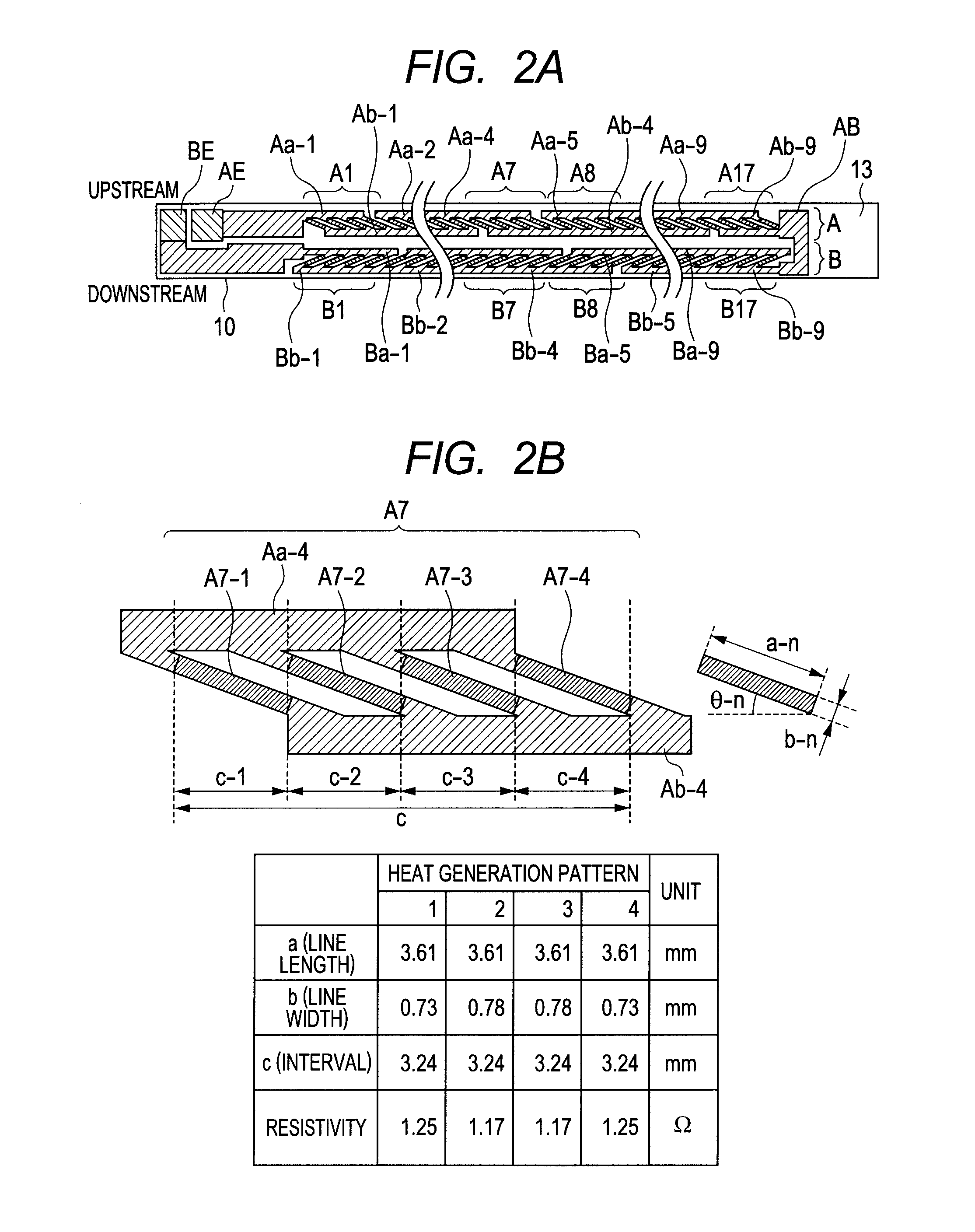
[0017]FIGS. 2A to 2C are views for illustrating a configuration of the heater 10. FIG. 2A is a plan view of the heater 10, FIG. 2B is an enlarged view illustrating a heat generation block A7 of heat generation blocks in the heat generation line A, and FIG. 2C is an enlarged view illustrating a heat generation block A8 of heat generation blocks in the heat generation line A. Note that, a heat generation resistor in the heat generation line A and a heat generation resistor in the heat generation line B both have PTC.

[0018]The heat generation line A (first line) includes seventeen heat generation blocks A1 to A17, and the heat generation blocks A1 to A17 are connected in series. The heat generation line B (second line) also includes seventeen heat generation blocks B1 to B17, and the heat generation blocks B1 to B17 are also connected in series. Further, the heat generation line A and the heat generation line B are also electrically connected in series through a conductive pattern AB. ...

second embodiment

[0034]FIG. 5 is a configuration diagram of a heater 20 according to a second embodiment. The heater 20 is different from the heater 10 of the first embodiment in that the heat generation resistors in the heat generation line A and in the heat generation resistor B are all inclined in the same direction. However, in the heater 20, the conductive patterns (Ba, Bb) in the heat generation line B are elaborated in shape. Thus, similarly to the heater 10 of the first embodiment, the first line and the second line are arranged so that one first heat generation block as a whole in the first line (heat generation line A) and one second heat generation block as a whole in the second line (heat generation line B) are substantially overlap each other in the longitudinal direction and one second heat generation block as a whole in the first line and one first heat generation block as a whole in the second line are substantially overlap each other in the longitudinal direction. Specifically, in t...


PUM


Abstract

The image heating apparatus includes first and second lines having a first and second heat generation blocks, the first and second lines being disposed at different positions in a transverse direction, wherein the first and second lines are arranged so that a whole of first heat generation block in the first line and a whole of second heat generation block in the second line overlap with each other in the longitudinal direction, and a whole of second heat generation block in the first line and a whole of first heat generation block in the second line overlap with each other in the longitudinal direction. By the virtue of the present invention, it achieves to be capable of suppressing a temperature rise in a non-sheet feeding area in a case of printing a sheet smaller in size than a maximum size supported by the image heating apparatus.

Description

TECHNICAL FIELD[0001]The present invention relates to a heater that can be suitably applied to a heat fixing apparatus to be installed in an image forming apparatus such as an electrophotographic copying machine or an electrophotographic printer, and an image heating apparatus having the heater installed therein.BACKGROUND ART[0002]There are known fixing apparatus to be installed in a copying machine or a printer, including an endless belt, a ceramics heater that is in contact with an inner surface of the endless belt, and a pressure roller for forming a fixing nip portion together with the ceramic heater via the endless belt. When small size sheets are successively printed in an image forming apparatus having such a fixing apparatus installed therein, there occurs a phenomenon (temperature rise in a non-sheet feeding portion) in which a temperature gradually increases in an area having no sheet to pass therethrough, in a longitudinal direction of the fixing nip portion. If the temp...

Claims


Application Information

Patent Timeline
Patent Type & Authority Patents(United States)
IPC IPC(8): H05B3/03G03G15/20H05B3/10
CPCH05B3/0095G03G15/2082G03G2215/2035H05B1/0241G03G15/2042H05B3/46
Inventor SHIMURA, YASUHIRO
Owner CANON KK
Why Eureka
Try Eureka