Supercharge Your Innovation With Domain-Expert AI Agents!

Connector

a technology of connecting rods and connectors, applied in the direction of printed circuits, electrical apparatus, etc., can solve the problems of failure of electrical connection between contacts and pads, difficult to maintain electrical connection between connectors and substrates, and difficulty in repairing connected structures

Inactive Publication Date: 2014-03-11
FUJITSU COMPONENENT LTD
View PDF11 Cites 4 Cited by
  • Summary
  • Abstract
  • Description
  • Claims
  • Application Information

AI Technical Summary

Benefits of technology

The present invention provides a connector that can be securely connected to a substrate and easily repaired. The connector has two contacts that can slide on the substrate in opposite directions when pushed, ensuring a strong electrical connection. This design allows for reliable and efficient connection of electronic components to the substrate.

Problems solved by technology

However, for the connector in which the contacts are electrically connected to the pads of the substrate by reflowing or soldering, the following problem occurs.
Therefore, it is difficult to repair the connected structure by exchanging the connector with respect to the substrate.
Further, if the connector is connected and fixed to the substrate by screws, there may be a failure in electrical connection between the contacts and the pads as the pressure applied to the contacts and the pads is insufficient.
The result is that it becomes difficult to maintain the electrical connection between the connector and the substrate for which the repairing of the connected structure is possible.
For obtaining the space, the contacts of the connector may have an L shape and this may cause a large size of the structure especially when the connector includes plural lines of alignment of the contacts.

Method used


Image

  • Connector
  • Connector
  • Connector

Examples


Embodiment Construction

[0027]The invention will be described herein with reference to illustrative embodiments. Those skilled in the art will recognize that many alternative embodiments can be accomplished using the teachings of the present invention and that the invention is not limited to the embodiments illustrated for explanatory purposes.

[0028]It is to be noted that, in the explanation of the drawings, the same components are given the same reference numerals, and explanations are not repeated.

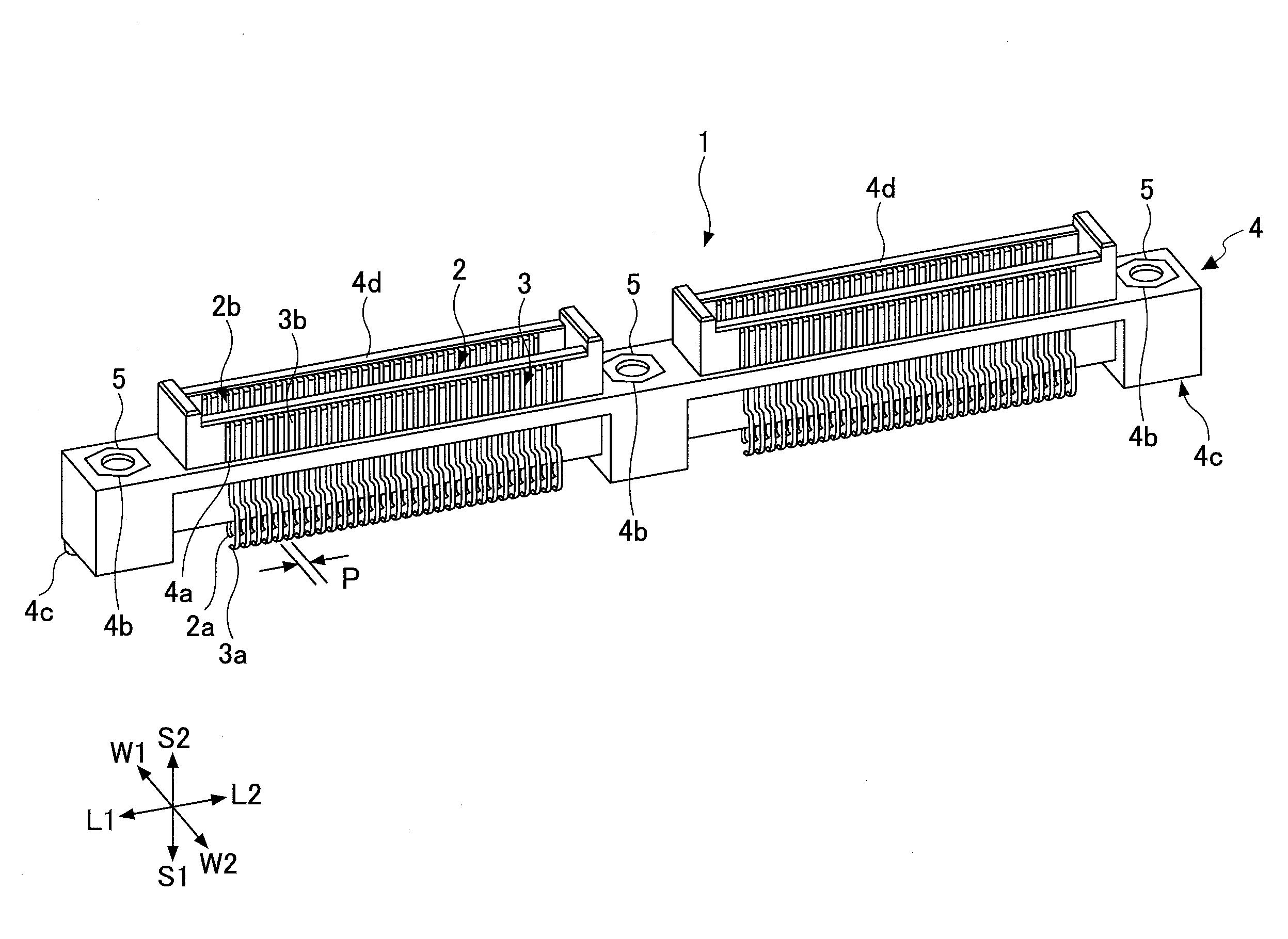
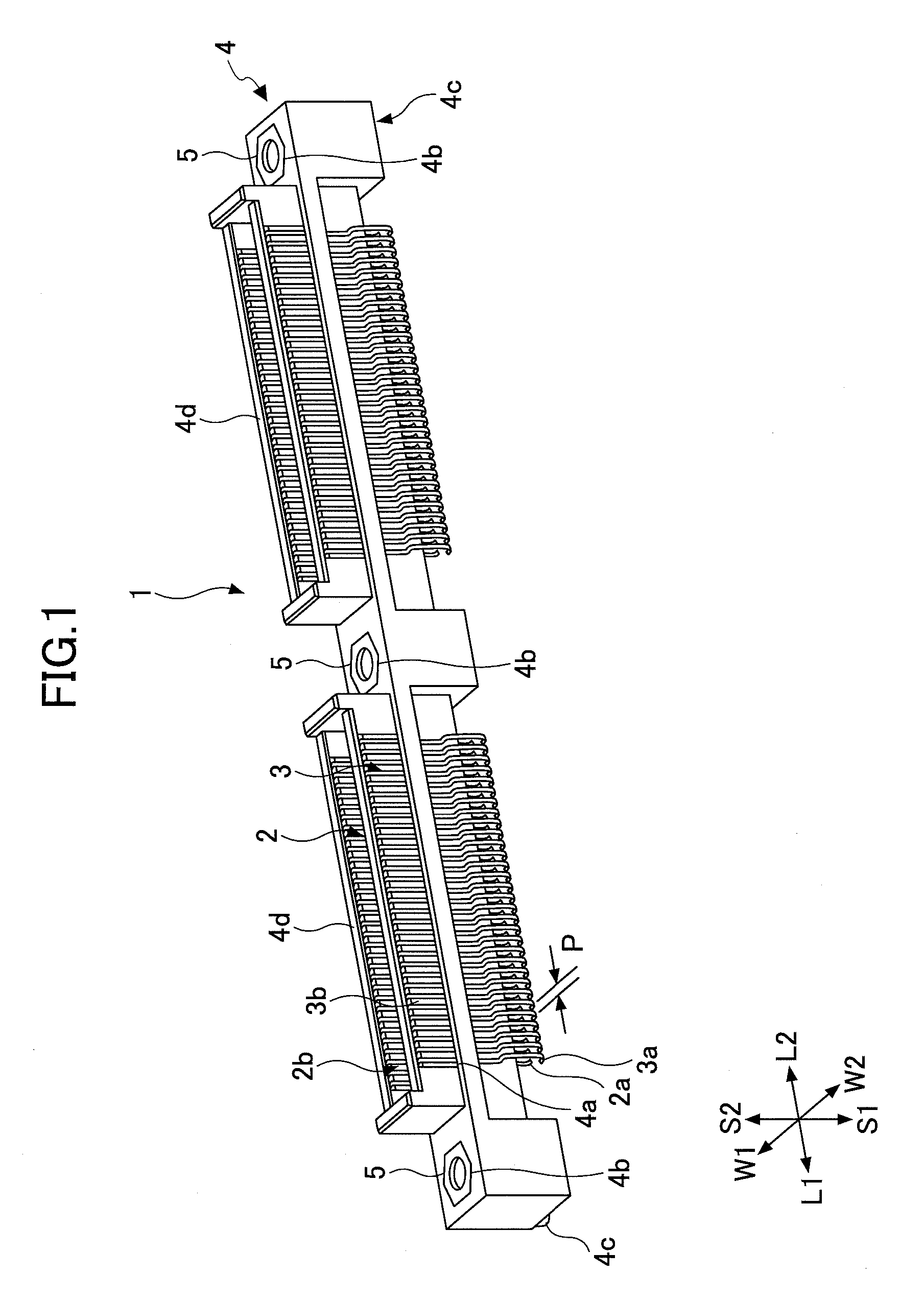
[0029]FIG. 1 is a perspective view showing an example of a connector 1 of the embodiment.

[0030]Hereinafter, the longitudinal direction of the connector 1 is referred to as a first alignment direction L1 and a second alignment direction L2, and the width direction of the connector 1 is referred to as a first width direction W1 and a second width direction W2. Further, the vertical downward direction in FIG. 1 is referred to as an approaching direction S1 and the vertical upward direction in FIG. 1 is referred to...


PUM


Abstract

A connector to be mounted on a substrate includes a first pad and a second pad formed on the surface, including a first contact including a first contacting portion to be in contact with the first pad when the connector is mounted on the substrate; and a second contact including a second contacting portion to be in contact with the second pad when the connector is mounted on the substrate, the first contact and the second contact being configured such that the first contacting portion slides on the first pad in a first direction while the second contacting portion slides on the second pad in a second direction opposite to the first direction, when the first contact and the second contact are pushed toward the first pad and the second pad, respectively, while the connector is being placed on and fixed to the substrate.

Description

BACKGROUND OF THE INVENTION[0001]1. Field of the Invention[0002]The present invention relates to a connector and more specifically, to a connector used for electrically connecting a home, an office or an industrial electronic device and a substrate or substrates in an electronic device.[0003]2. Description of the Related Art[0004]When electrically and detachably connecting a substrate and an electronic device, or connecting substrates in an electronic device, a connector including a power source, a signal conductor, a ground conductor, a shield conductor or the like is generally used. Japanese Patent No. 4,280,013 discloses such a connector.[0005]According to Japanese Patent No. 4,280,013, pads are aligned on a substrate to be connected and contacts are provided to correspond to the pads at a connector so that the contacts can respectively touch the pads when mounting the connector on the substrate.[0006]The connector disclosed in Japanese Patent No. 4,280,013, is provided with two ...

Claims


Application Information

Patent Timeline
Patent Type & Authority Patents(United States)
IPC IPC(8): H01R12/00
CPCH01R12/721H01R12/716
Inventor TAKAHASHI, KOKISATO, KOKIKOBAYASHI, MITSURU
Owner FUJITSU COMPONENENT LTD
Features
  • R&D
  • Intellectual Property
  • Life Sciences
  • Materials
  • Tech Scout
  • Unparalleled Data Quality
  • Higher Quality Content
  • 60% Fewer Hallucinations
Learn More