
Capacitive power supply

a capacitive power supply and power supply technology, applied in the direction of power conversion systems, instruments, electrical equipment, etc., can solve the problems of difficult inability to switch off the whole appliance, so as to facilitate the design of capacitive power supplies, the effect of variable characteristics of components

Active Publication Date: 2014-05-20
VERSUNI HLDG BV
View PDF39 Cites 4 Cited by
  • Summary
  • Abstract
  • Description
  • Claims
  • Application Information

AI Technical Summary

Benefits of technology

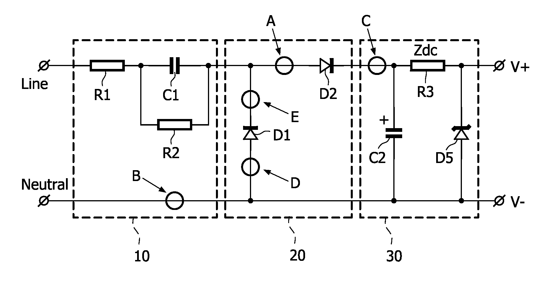
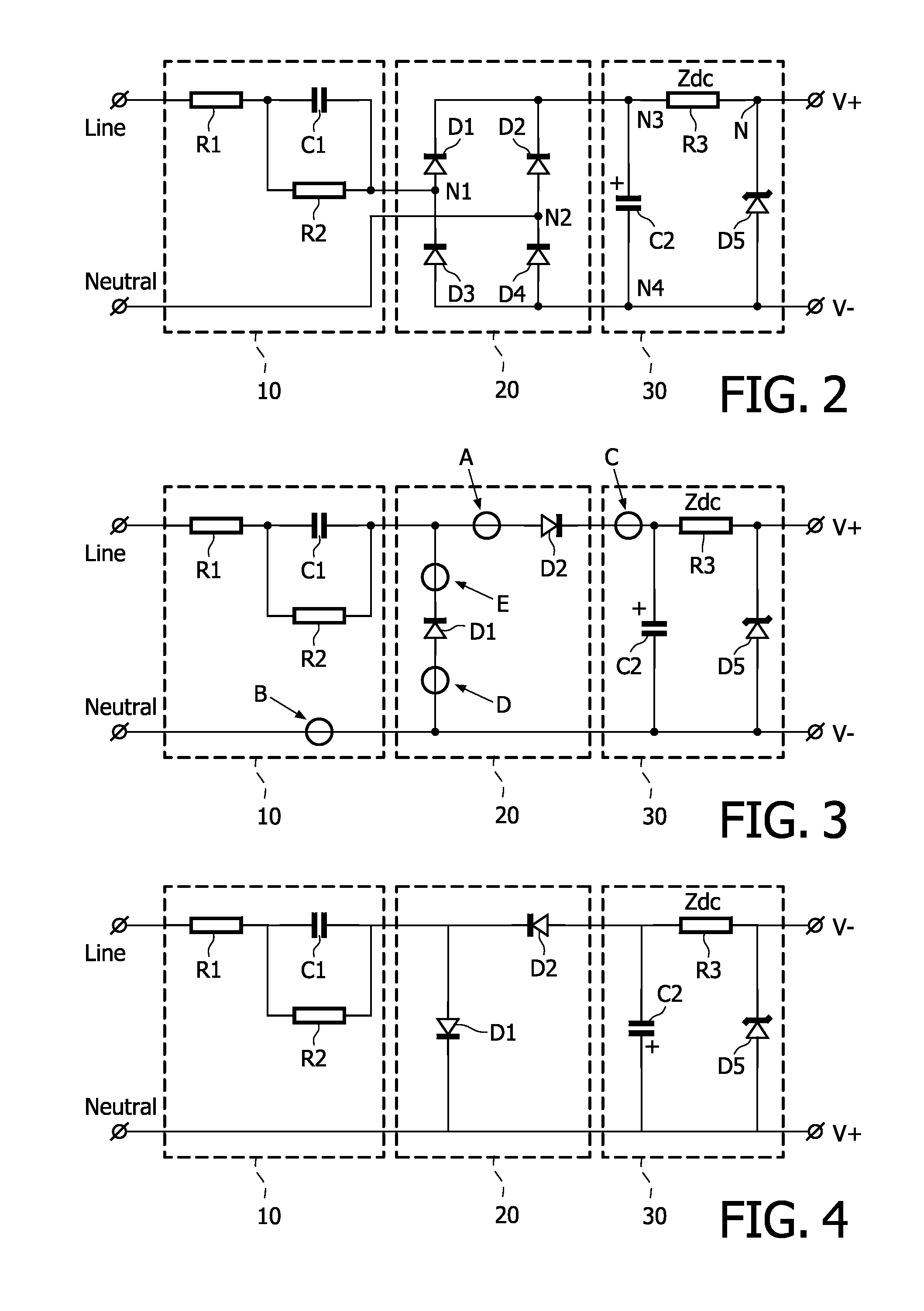
[0017]As the second chain includes a DC-conducting series impedance, with a resistance value R of at least 0.2 times a resistive value of the first chain, the stress imposed to the inrush current limiting facility is released. Accordingly a higher inrush current is allowed without causing damage to the output voltage limiting facility and any circuitry coupled to the output terminals. Surprisingly, in an advantageous embodiment, even a rather small value of the impedance of the DC-conducting impedance (e.g. 2.2Ω) appeared to make it possible to lower a resistive value used for inrush current limitation by far more than the value of the DC-conducting impedance, e.g. from 270Ω necessary in the absence of the DC-conducting impedance to prevent too high peak voltages at the output from occurring, to only 100Ω in the presence of the DC-conducting impedance of 2.2Ω, without risking too high peak voltages. As the lower the inrush resistance is, the lower the power dissipation, this allows for a reduced resistive inrush current limitation, and thereby a reduced power dissipation of the capacitive power supply without requiring a more robust dimensioning of the voltage limiting facility. In particular embodiments the DC-conducting series impedance may even have a resistance substantially lower that the resistance of the inrush current limiting facility, thereby resulting in a substantial reduction of the dissipated power.
[0021]Preferably therefore the DC-conducting series impedance (Zdc) has a resistive value R of at least 10 times a resistive value of the first chain. In this way the application in a mass fabrication process, where in practice variations occur in the characteristics of the components, is facilitated.

Problems solved by technology

For various household appliances it is not possible to switch off the whole appliance, due to convenience of use or technical reasons.
Due to regulations and the desire for green electronic designs, however, standby power consumption of appliances should be limited to a minimum.
In practice it is difficult to design the capacitive power supply such that the phase shift is exactly 90 degrees, as account has to be taken of additional constraints.
One thereof is that the inrush current of the device, occurring if the device is attached to the mains or switched on by a mains switch, is limited to value at which damage to the supply is prevented.
It must be prevented that this deviations ripple through too much as variations into the voltage supplied by the capacitive power supply, and therewith may cause undesired situations.
As a negative side effect however this series resistance dissipates power.

Method used


Image

  • Capacitive power supply
  • Capacitive power supply
  • Capacitive power supply

Examples


Embodiment Construction

[0030]In the following detailed description numerous specific details are set forth in order to provide a thorough understanding of the present invention. However, it will be understood by one skilled in the art that the present invention may be practiced without these specific details. In other instances, well known methods, procedures, and components have not been described in detail so as not to obscure aspects of the present invention.

[0031]A single component or other unit may fulfill the functions of several items recited in the claims. The mere fact that certain measures are recited in mutually different claims does not indicate that a combination of these measures cannot be used to advantage. Any reference signs in the claims should not be construed as limiting the scope.

[0032]It will be understood that when an element is referred to as being coupled to another element, it can be directly connected to the other element but alternatively intervening elements may be present bet...


PUM


Abstract

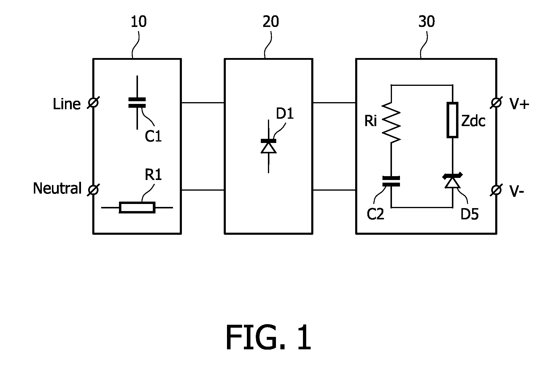
A capacitive power supply including an input section having input terminals for connection to an AC-mains supply, and a capacitive coupling, a rectification section coupled via the capacitive coupling to the input terminals, and an output section coupled to the rectification section, the output section including output terminals, for providing an output voltage to a load, a first chain including a charge storage facility, and a second chain arranged in parallel to the first chain, and including an output voltage limiting facility, the capacitive power supply further including an inrush current limiting facility, wherein the output terminals are connected to respective terminals of the output voltage limiting facility, and the DC-conducting series impedance has a resistive component with a resistive value of at least 0.2 times a resistive value of the first chain.

Description

FIELD OF THE INVENTION[0001]The invention relates to a capacitive power supply. The invention further relates to an electronic device provided with a capacitive power supply.BACKGROUND OF THE INVENTION[0002]For various household appliances it is not possible to switch off the whole appliance, due to convenience of use or technical reasons. For example, in video and audio equipment it is desirable that the device remains standby so that is capable of receiving and processing remote control signals. Or the device may have a permanently active control clock for activating other modules of the device at a predetermined time.[0003]Due to regulations and the desire for green electronic designs, however, standby power consumption of appliances should be limited to a minimum.[0004]Often a capacitive power supply is used to supply the part of the electronics inside the appliance that should remain permanently active. The appliance may for example be a coffee-maker or a washing-machine, havin...

Claims


Application Information

Patent Timeline
Patent Type & Authority Patents(United States)
IPC IPC(8): H02H7/125H02M7/08
CPCH02M7/062H02M7/05
Inventor DE, HAAN, THIJS
Owner VERSUNI HLDG BV
Learn More