Medical implant with floating magnets

Active Publication Date: 2014-05-27
TORAX MEDICAL
View PDF5 Cites 60 Cited by
  • Summary
  • Abstract
  • Description
  • Claims
  • Application Information

AI Technical Summary

Benefits of technology

[0005]The magnetic elements and / or housings can be of any shape and size so long as the magnetic elements are allowed to float or rotate within the casing. Additionally, any number of magnetic elements can be used within a single housing so long as the magnetic elements are allowed to float or align with whatever external magnetic field is strongest. Furthermore, the housings can be linked together in any suitable way, as long as the implant is sufficiently flexible to interact with body organs and / or tissue as intended. Such a flexible linkage, or the members making up the flexible linkage, can be made from polymers, metals, textiles, etc. The flexible linkage serves to allow the individual housings to move apart from each other when external forces overcome the attractive forces between magnetic elements within adjacent housings of the medical implant. In some embodiments, the flexible linkage should also serve to limit the allowable separation distance between the housings of the medical implant.
[0007]In each of these embodiments, in the absence of a strong external magnetic field, the magnetic fields of the magnetic elements within the medical implant will predominate, attracting the housings to one another to perform the desired medical function. In some embodiments, in the presence of a strong external magnetic field, such as that of an MRI scanner, the magnetic elements may rotate within the housings to align with the stronger field. While the magnetic elements may, therefore, not perform the desired medical function during that time, the flexible member will prevent the implant from completely failing, and the implant will be able to resume its function once the strong external magnetic field is removed.

Problems solved by technology

Additionally, to ensure that excessive tissue ingrowth into or about the housings and / or flexible linkages of the medical implant does not prevent the medical implant from functioning as intended, the surfaces of the housings and / or the flexible linkages may be coated with one or more polymers, drugs, or biologics to modulate tissue growth.

Method used


Image

  • Medical implant with floating magnets
  • Medical implant with floating magnets
  • Medical implant with floating magnets

Examples


Embodiment Construction

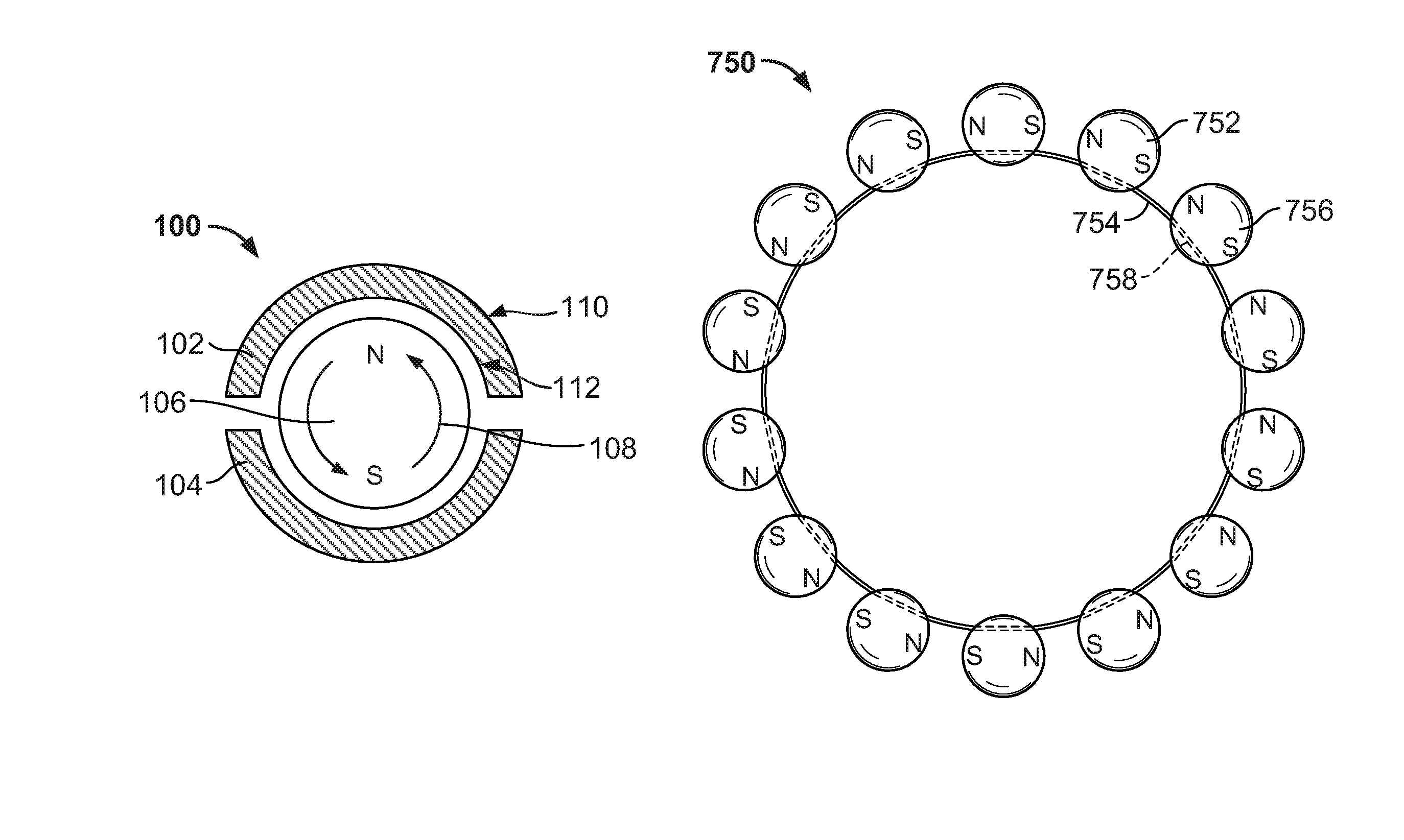
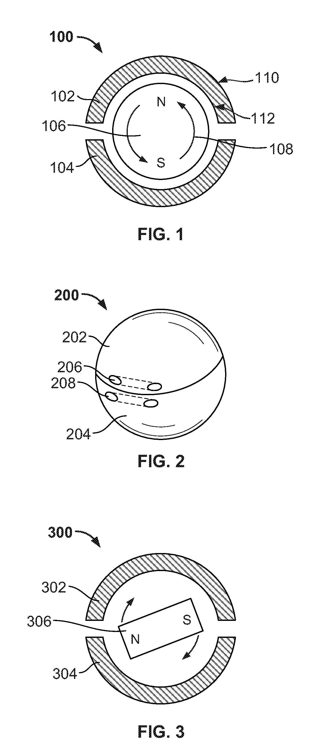
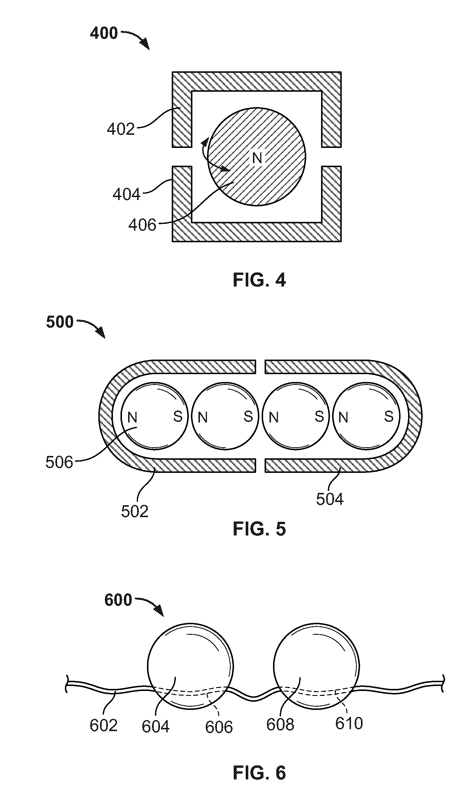
[0030]Systems and methods are described for the use of “floating” magnetic elements in medical implants. The medical implant includes a series of housings, which encapsulate the magnetic elements. Each housing allows its respective magnetic element or elements to rotate freely in order to align with the magnetic fields of magnetic elements in adjacent housings of the medical implant or magnetic fields external to the medical implant. The housings are connected by a flexible linkage, which engages each of the housings, but which does not impair the rotation of the magnetic elements within the housings. The flexible linkage may also accommodate the various circumferential sizes associated with the medical implant.

[0031]The medical implant may include a pressure-mediated device placed around a patient's tissue structure, body organ, or body lumen to control the rate of fluid, solid, or other content passage through the tissue structure. The tissue structure may be, for example, the eso...


PUM


Abstract

Systems and methods are described for the use of floating magnetic elements in medical implants. The magnetic elements within the medical implant are allowed to rotate freely to align with a strong external magnetic field, such as that of an MRI scanner, and align to attract each other during the normal functioning of the medical implant in the absence of a strong external magnetic field.

Description

CROSS REFERENCE TO RELATED APPLICATION[0001]This claims the benefit of copending, commonly-assigned U.S. Provisional Patent Application No. 61 / 526,314, filed Aug. 23, 2011, which is hereby incorporated by reference herein in its entirety.BACKGROUND OF THE INVENTION[0002]This invention relates to medical implants containing magnetic material placed around a tissue or body structure, where the medical implant can be made more compatible with competing magnetic fields, such as those present during Magnetic Resonance Imaging (MRI), by employing “floating” magnets.[0003]Strong magnetic fields such as those within an MRI scanner can cause magnetic material in a medical implant to depolarize or repolarize, and also can induce undesirable forces on the medical implant. The magnetic field may induce a torsional force that attempts to align the magnetic poles within the implant to the magnetic field. This force can result in undesirable stress on the patient's body tissues, or on the implant ...

Claims


Application Information

Patent Timeline
Patent Type & Authority Patents(United States)
IPC IPC(8): A61B17/08
CPCA61N2/06A61B17/12013A61B2017/00827A61F2210/009A61B2017/00876A61B17/08A61N2/004A61F5/005
Inventor EKVALL, CRAIG A.WHITBROOK, ERIC
Owner TORAX MEDICAL
Why Eureka
Try Eureka