Magnetic firearm support

a magnetic and firearm technology, applied in the field of magnetic firearm supports, can solve the problems of cumbersome removal of firearms from safes, cumbersome placing of firearms in safes for storage, and inadvertent falling of firearms

Active Publication Date: 2014-06-03
CONNER BARRY WAYNE MR +1
View PDF35 Cites 40 Cited by
  • Summary
  • Abstract
  • Description
  • Claims
  • Application Information

AI Technical Summary

Problems solved by technology

One of the drawbacks of storing long firearms in conventional firearm safes is that the firearms may have a tendency to inadvertently fall over if not appropriately secured.
Moreover, removal of the firearm from the safe may be cumbersome since the stock of the firearm may be inserted in a slot in the lower portion of the safe.
Placing a firearm in the safe for storage may be equally cumbersome.

Method used


Image

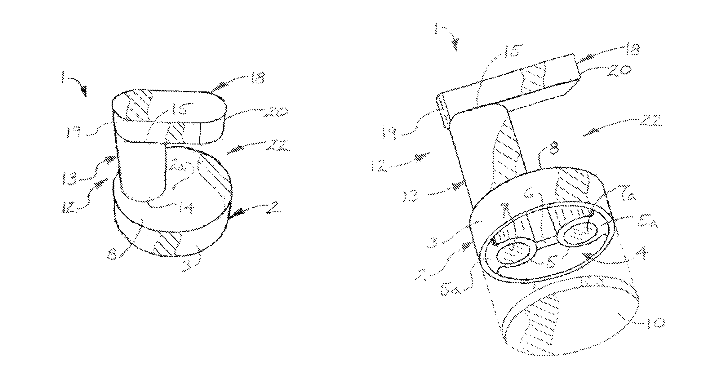
  • Magnetic firearm support
  • Magnetic firearm support
  • Magnetic firearm support

Examples


Embodiment Construction

[0013]The following detailed description is merely exemplary in nature and is not intended to limit the described embodiments or the application and uses of the described embodiments. As used herein, the word “exemplary” or “illustrative” means “serving as an example, instance, or illustration.” Any implementation described herein as “exemplary” or “illustrative” is not necessarily to be construed as preferred or advantageous over other implementations. All of the implementations described below are exemplary implementations provided to enable persons skilled in the art to practice the disclosure and are not intended to limit the scope of the appended claims. Moreover, the illustrative embodiments described herein are not exhaustive and embodiments or implementations other than those which are described herein and which fall within the scope of the appended claims are possible. Furthermore, there is no intention to be bound by any expressed or implied theory presented in the precedi...


PUM


Abstract

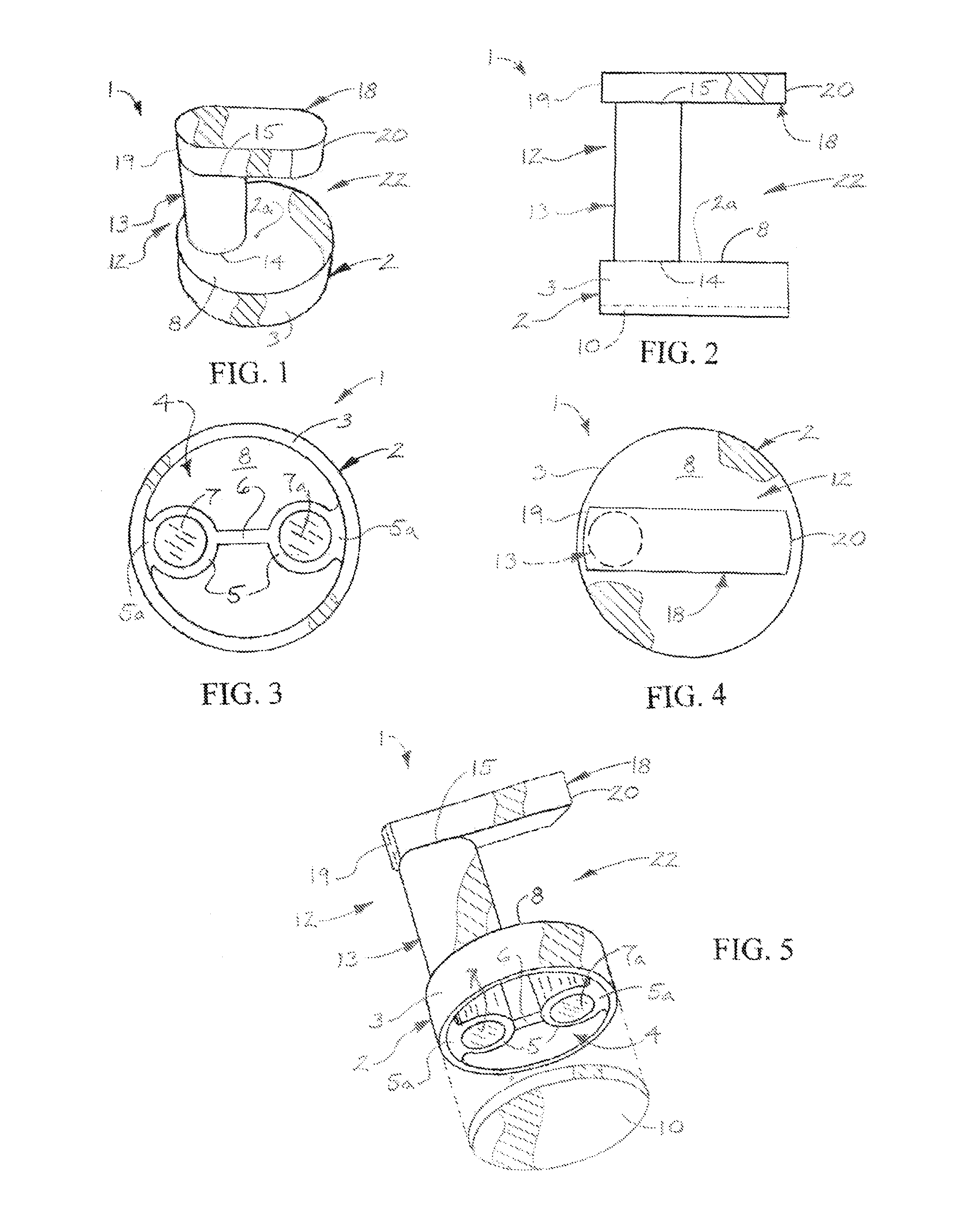
A magnetic firearm support includes a base, at least one magnet in the base and a firearm cradle having a firearm space carried by the base.

Description

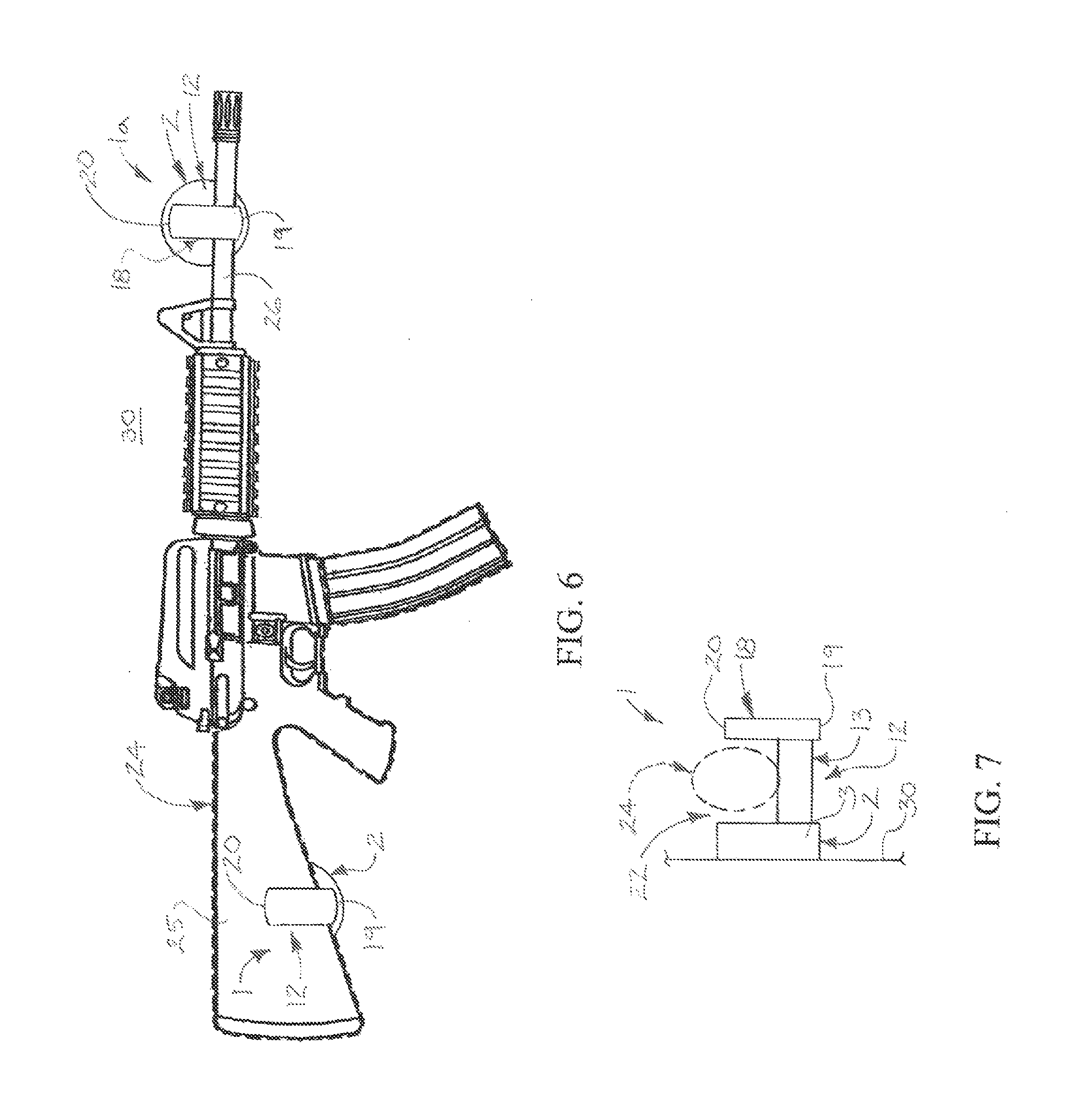
FIELD OF THE INVENTION[0001]Illustrative embodiments of the disclosure generally relate to supports for firearms. More particularly, illustrative embodiments of the disclosure relate to a magnetic firearm support which is suitable for supporting a firearm on any ferrous metal surface (steel) such as the interior door or wall of a firearm safe.BACKGROUND OF THE INVENTION[0002]Firearms including pistols and long firearms such as rifles are commonly stored in a vertical position in a firearm safe. One of the drawbacks of storing long firearms in conventional firearm safes is that the firearms may have a tendency to inadvertently fall over if not appropriately secured. Moreover, removal of the firearm from the safe may be cumbersome since the stock of the firearm may be inserted in a slot in the lower portion of the safe. Removal of a firearm from the rear portion of the safe may require that firearms in the front portion of the safe be removed to clear a path for removal of the firearm...

Claims


Application Information

Patent Timeline
Patent Type & Authority Patents(United States)
IPC IPC(8): F41A23/18A47B81/00B60R11/00
CPCB60R7/14F41A23/18
Inventor CONNER, BARRY, WAYNE
Owner CONNER BARRY WAYNE MR
Why Eureka
Try Eureka