Surgical instrument having a plastic surface

a surgical instrument and plastic surface technology, applied in the direction of surgical forceps, surgical staples, manufacturing tools, etc., can solve the problem of requiring a relatively large amount of force to be applied to the movable handle, and achieve the effect of low friction coefficient and low friction coefficien

Active Publication Date: 2014-07-08
TYCO HEALTHCARE GRP LP
View PDF505 Cites 1068 Cited by
  • Summary
  • Abstract
  • Description
  • Claims
  • Application Information

AI Technical Summary

Problems solved by technology

A large frictional force may be present between the closure apparatus and the contact surface of the tool assembly, thus possibly requiring a relatively large amount of force to be applied to the movable handle.

Method used


Image

  • Surgical instrument having a plastic surface
  • Surgical instrument having a plastic surface
  • Surgical instrument having a plastic surface

Examples


Embodiment Construction

[0053]Embodiments of the presently disclosed surgical instrument and DLU will now be described in detail with reference to the drawings, in which like reference numerals designate identical or corresponding elements in each of the several views.

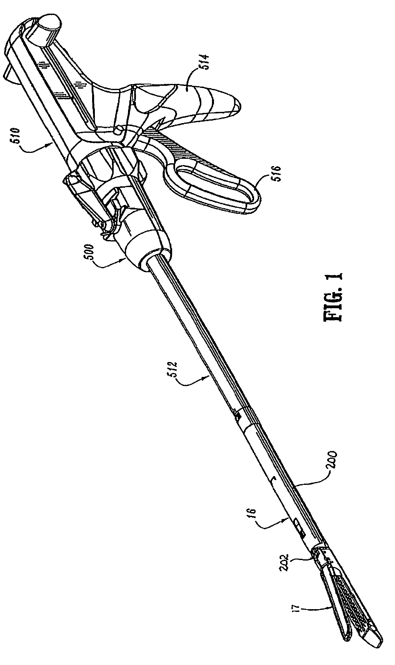
[0054]Referring to FIG. 1, surgical instrument 500 includes a handle portion 510, a body portion 512, and a disposable loading unit (“DLU”) 16. Handle portion 510 includes a stationary handle 514 and a movable handle or trigger 516. Movable handle 516 is movable in relation to stationary handle 514 to advance a control rod 520 which projects from the distal end of body portion 512. Handle portion 510 and body portion 512 may be constructed in the manner disclosed in U.S. Pat. No. 6,330,965 which is hereby incorporated herein in its entirety by reference. Alternately, other surgical instruments can be used with DLU 16 to perform endoscopic surgical procedures.

[0055]Referring to FIGS. 1 and 1A, briefly, DLU 16 includes a tool assembly 17, a pro...


PUM

PropertyMeasurementUnit
metallicaaaaaaaaaa
non-metallicaaaaaaaaaa
lengthaaaaaaaaaa

Abstract

A surgical instrument including a handle portion, a body portion, a movable handle, a tool assembly, a drive beam and a closure apparatus is disclosed. At least one of the closure apparatus and a contact surface of the tool assembly include a plastic surface. The body portion extends distally from the handle portion. The movable handle is located on the handle portion and is in mechanical cooperation with a drive member. The tool assembly includes an anvil, a cartridge assembly and a contact surface. The drive beam includes a proximal engagement portion and is configured to engage a portion of the drive member. The closure apparatus is configured to engage the contact surface of the tool assembly. At least a partial actuation of the movable handle moves the closure apparatus distally into engagement with the contact surface to approximate the anvil and the cartridge assembly.

Description

CROSS-REFERENCE TO RELATED APPLICATIONS[0001]This application is a continuation of U.S. patent application Ser. No. 12 / 962,887, filed on Dec. 8, 2010 now U.S. Pat. No. 8,245,900, which is a divisional of U.S. patent application Ser. No. 12 / 198,948, filed on Aug. 27, 2008 now U.S. Pat. No. 7,866,525, which claims the benefit of, and priority to, U.S. Provisional Patent Application Ser. No. 60 / 967,190, filed on Aug. 31, 2007, now expired, and is a continuation-in-part of U.S. patent application Ser. No. 11 / 544,982, filed on Oct. 6, 2006 now U.S. Pat. No. 7,845,535, the entire contents of each of the above-identified applications being incorporated by reference herein in their entirety.BACKGROUND[0002]1. Technical Field[0003]The present disclosure relates to a surgical instrument and disposable loading unit including a plastic surface thereon. More particularly, the present disclosure relates to a surgical instrument which includes a plastic surface on at least one of a closure apparat...

Claims


Application Information

Patent Timeline
Patent Type & Authority Patents(United States)
IPC IPC(8): A61B17/04A61B17/10
CPCA61B2017/00845A61B2017/2946B29C45/14344A61B17/068A61B17/07207A61B2017/320052A61B2017/0023A61B2017/2936A61B2017/2927A61B2017/0046A61B2017/00128A61B2017/07214A61B17/105A61B2017/00473A61B2017/07285
Inventor SCIRICA, PAUL
Owner TYCO HEALTHCARE GRP LP
Why Eureka
Try Eureka