Musical instrument stand

Inactive Publication Date: 2014-07-08
YU TSUNG YAO
View PDF6 Cites 12 Cited by
  • Summary
  • Abstract
  • Description
  • Claims
  • Application Information

AI Technical Summary

Benefits of technology

The present invention is a musical instrument stand that has several advantages. Firstly, the support unit is pivotally mounted on the bottom bar of the frame unit, which makes it easy for users to place the musical instrument on the stand and push it towards the top bar. This saves time and makes it simple for users to set up the stand. Secondly, the musical instrument is placed directly on the support unit and the top bar of the frame unit, so users don't have to align the musical instrument with the top bar. This makes it easier for users to set up the stand. Thirdly, the support unit automatically returns to its initial position after the musical instrument is removed, which ensures the safety of the placement of the musical instrument. Fourthly, the frame unit is designed in an inclined manner, which ensures solid and stable support of the musical instrument, preventing it from falling out of the stand. Fifthly, the parts of the frame unit can be detached, which decreases the cost of packaging, transportation, and storage of the stand. Lastly, the number of support units can be adjusted according to the user's requirement, enhancing the versatility of the stand.

Problems solved by technology

However, the bottom bars 12 and the top bar 13 are fixed and cannot be adjusted to fit the position of the musical instrument 14, so that when the musical instrument 14 is not placed between the bottom bars 12 and the top bar 13 steadily and stably, the musical instrument 14 easily slips or falls out of the conventional musical instrument stand 1 due to an unsteady center of gravity, and will be worn or broken due to hit.
In addition, it is necessary to align the musical instrument 14 with the separation members 132 so as to insert the musical instrument 14 between any two of the separation members 132, thereby causing inconvenience to the user when placing and taking the musical instrument 14.

Method used


Image

  • Musical instrument stand
  • Musical instrument stand
  • Musical instrument stand

Examples


Embodiment Construction

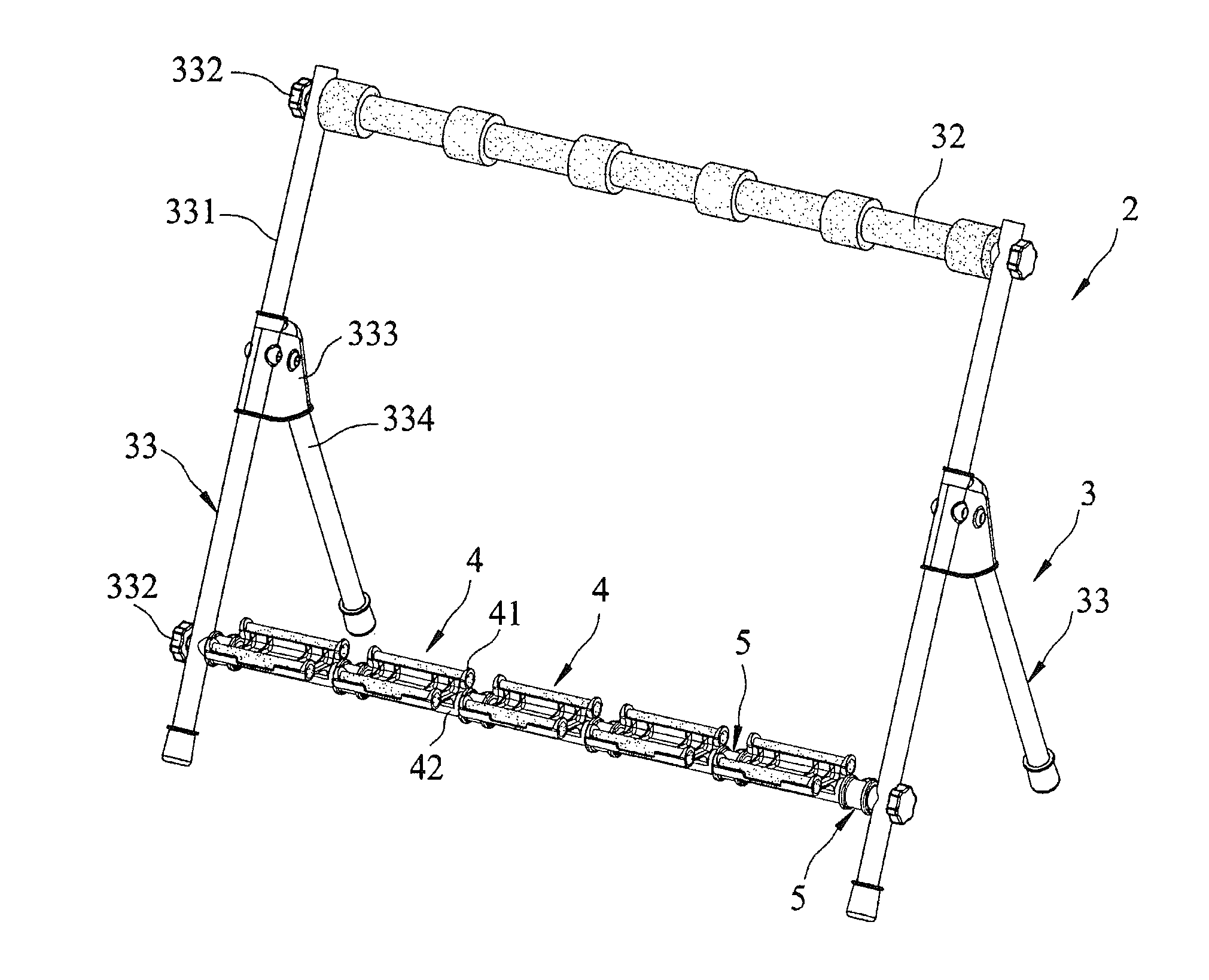
[0029]Referring to the drawings and initially to FIGS. 3-7, a musical instrument stand 2 in accordance with the preferred embodiment of the present invention comprises a frame unit 3, at least one support unit 4 mounted on the frame unit 3, and at least one spacer 5 mounted on the frame unit 3 and abutting the support unit 4.

[0030]The frame unit 3 includes two side modules 33 spaced from each other, a top bar 32 mounted between the side modules 33, and a bottom bar 31 mounted between the side modules 33 and located under the top bar 32.

[0031]Each of the side modules 33 of the frame unit 3 includes a side bar 331 abutting the top bar 32 and the bottom bar 31, two connectors 332 each detachably locked onto the side bar 331 and each connected with a respective one of the top bar 32 and the bottom bar 31, a connecting seat 333 detachably mounted on the side bar 331, and a support bar 334 detachably connected with the connecting seat 333 and inclined relative to the side bar 331 to suppo...


PUM


Abstract

A musical instrument stand includes a frame unit, and at least one support unit. The frame unit includes two side modules, a top bar mounted between the side modules, and a bottom bar mounted between the side modules. The support unit includes a supporting seat for supporting a musical instrument, and a mounting sleeve connected with the supporting seat and rotatably mounted on the bottom bar of the frame unit. Thus, the support unit is pivotally mounted on the frame unit, so that a user only needs to place the musical instrument on the support unit and to push the musical instrument toward the top bar of the frame unit, so as to pivot the support unit and to support the musical instrument between the top bar of the frame unit and the supporting seat of the support unit.

Description

BACKGROUND OF THE INVENTION[0001]1. Field of the Invention[0002]The present invention relates to a stand and, more particularly, to a musical instrument stand.[0003]2. Description of the Related Art[0004]A conventional musical instrument stand 1 in accordance with the prior art shown in FIGS. 1 and 2 comprises two side frames 11, a top bar 13, and two bottom bars 12. Each of the side frames 11 has a substantially L-shaped profile and has an upright bar 112 and a transverse bar 111. The top bar 13 is mounted between the side frames 11 and includes a mounting sleeve 131 mounted between the upright bars 112 of the side frames 11, and a plurality of separation members 132 mounted on the mounting sleeve 131. Each of the bottom bars 12 is mounted between the transverse bars 111 of the side frames 11. In use, when a musical instrument 14, such as a guitar and the like, is placed on the musical instrument stand 1, the bottom of the musical instrument 14 is located between the bottom bars 12...

Claims


Application Information

Patent Timeline
IPC IPC(8): G10G5/00A47B23/00
CPCG10G5/00
Inventor YU, TSUNG-YAO
Owner YU TSUNG YAO
Why Eureka
Try Eureka