Adjustable camera flash mounting device

Active Publication Date: 2014-07-08
MUZILA MICHAEL
View PDF13 Cites 14 Cited by
  • Summary
  • Abstract
  • Description
  • Claims
  • Application Information

AI Technical Summary

Benefits of technology

[0009]An adjustable camera flash mounting bracket device that provides for an integrated repositioning of a mounted camera flash in regards to a fixed mounted camera. The orientation of the independently adjustable camera flash vis-à-vis the camera is achieved by a movable flash mounting base having a curved interconnected armature with an internal guide and resistant inducing guide elements affording incremental and pre-determined fixed interengagement fixation points therebetween. The combination of the guide and pressure gripping contact between the rotatable guide surfaces and the guide channels within the flash mount assures slidable gripping contact and therefore positioning therebetween without changing the relative orientation of the camera so positioned within the bracket structure by encompassing a moving orientation of the flash mount to maintain the flash at a desired position to the subject matter.

Problems solved by technology

While this typically creates no physical problems for the photographer, such camera rotation usually results in the rotation of the associated flash unit that is either physically attached to the camera or to a bracket that is attached to the camera.
When the angular orientation of the flash unit is changed, side shadows, which are undesirable, may be introduced into the resulting photograph.

Method used


Image

  • Adjustable camera flash mounting device
  • Adjustable camera flash mounting device
  • Adjustable camera flash mounting device

Examples


Embodiment Construction

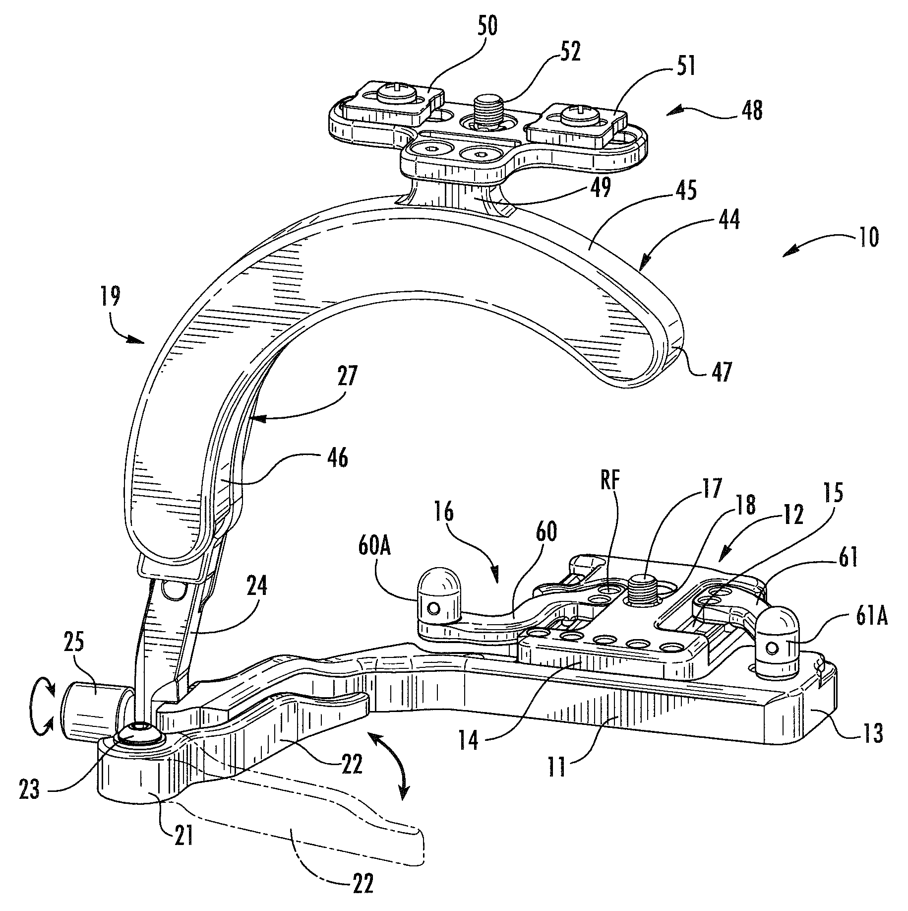
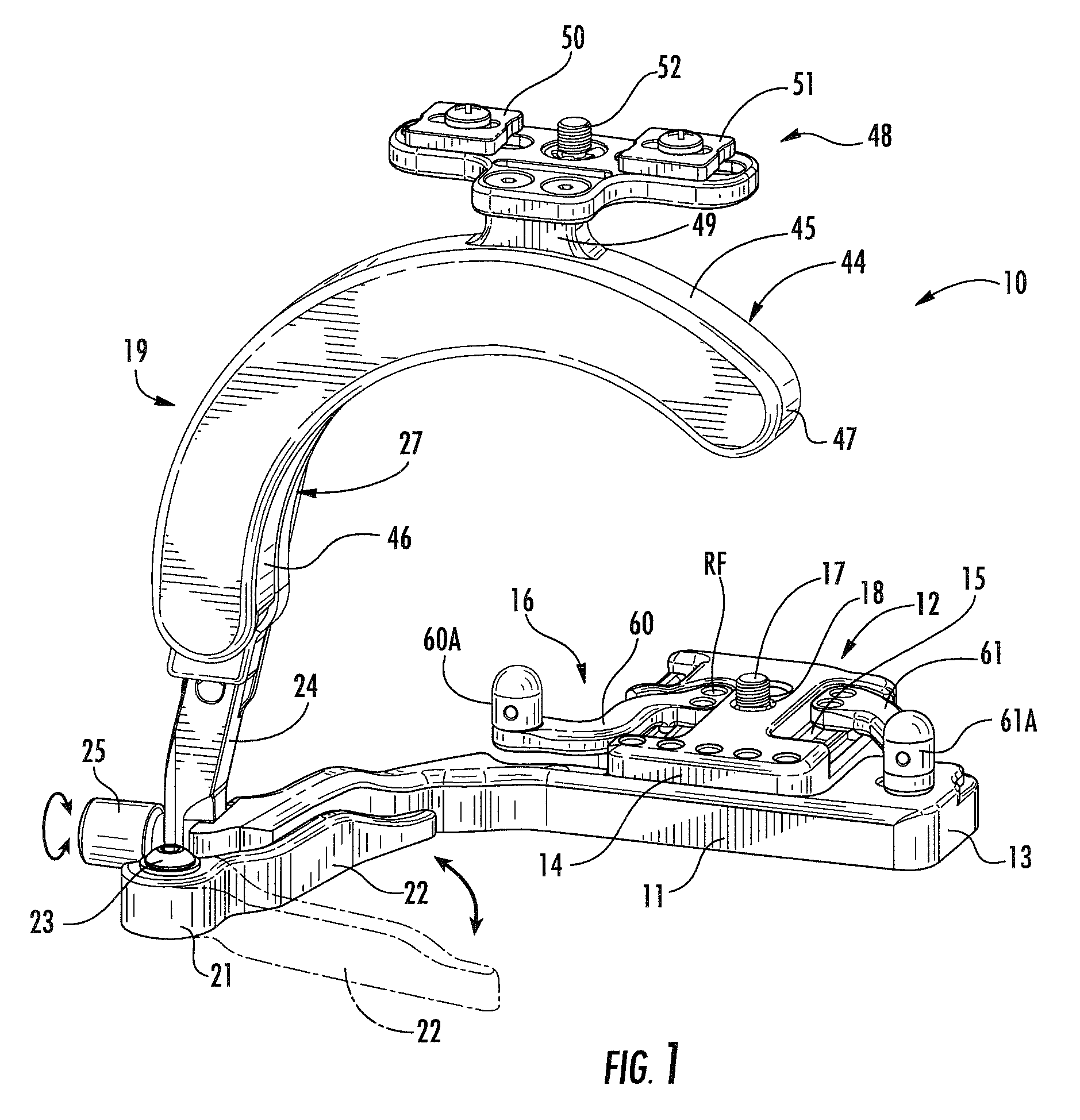
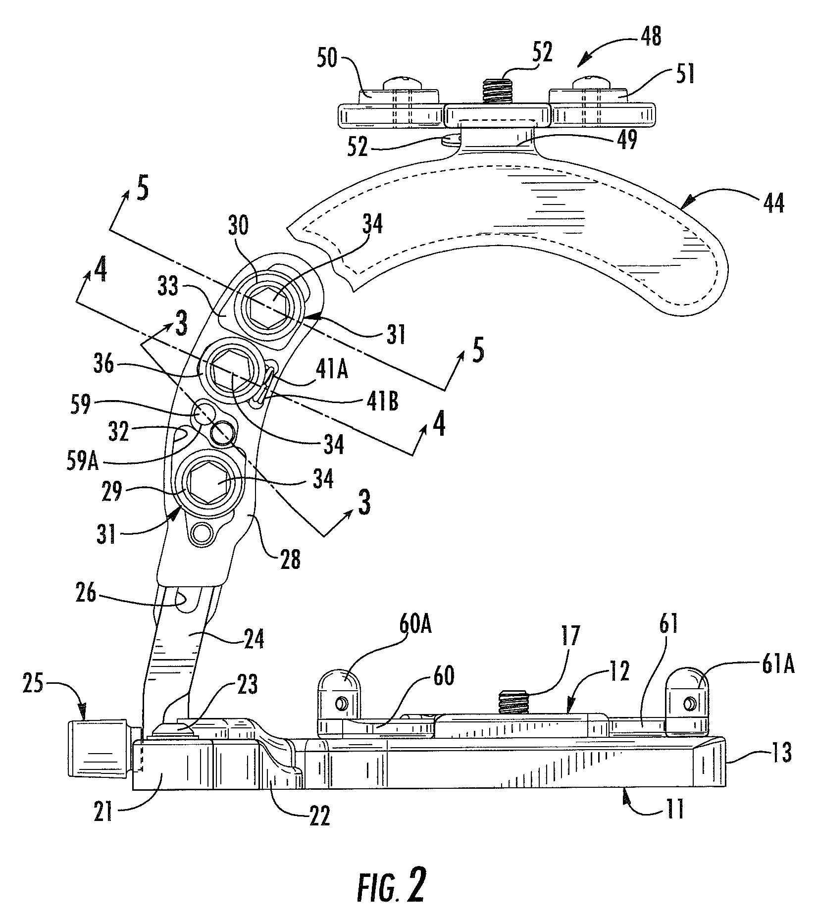
[0019]Referring now to FIGS. 1, 2, 7 and 8 of the drawings, an adjustable camera flash mounting device 10 of the invention can be seen having a base member 11 with a camera mounting assembly 12 secured inwardly from one end thereof. The camera mounting assembly 12 has an apertured support base 14 with multiple engagement slots 15 extending therethrough for adjustably receiving camera positioning arm elements 16. A central threaded camera attachment fitting 17 extends freely and rotatably through a central bore 18 in the platform 14 to selectively engage and secure a camera, not shown, thereto as will be understood by those skilled in the art and as will be described in greater detail hereinafter.

[0020]A camera flash mounting assembly 19 of the invention is mounted on and extends from the base member 11 inwardly of its oppositely disposed free end 21. An adjustable base stabilization arm 22 is pivotally secured by a threaded pivot pin 23 to the base and can therefore be selectively e...


PUM


Abstract

An adjustable camera flash mounting bracket device for rapid camera flash repositioning in relation to a camera attachment platform in selective orientation. The camera flash mounting bracket device includes a camera receiving base with a curved spaced upstanding camera flash mounting platform assembly having a complimentary curved flash engagement configuration. Multiple rotatable guide members are secured within the curved flash engagement portion and are received within complimentary grooves in the flash mounting base. Retainment force applied by spring urged guide members permits for selective rotation within the curved flash mounting base to be grippingly retained therewithin at user select position orientation in relation to the fixed camera mount.

Description

BACKGROUND OF THE INVENTION[0001]1. Technical Field[0002]The present invention relates to adjustable camera flash mounts that provide for camera flash positioning adjustments in relation to the orientation of the camera on multiple planes.[0003]2. Description of Prior Art[0004]Both amateur and professional photographers have occasion to rotate their cameras from a horizontal position to a vertical position or any position therebetween to obtain a desired photograph of the subject matter. While this typically creates no physical problems for the photographer, such camera rotation usually results in the rotation of the associated flash unit that is either physically attached to the camera or to a bracket that is attached to the camera. When the angular orientation of the flash unit is changed, side shadows, which are undesirable, may be introduced into the resulting photograph. It should be noted that shadows behind the subject are desirable and such shadows can be produced when the f...

Claims


Application Information

Patent Timeline
Patent Type & Authority Patents(United States)
IPC IPC(8): G03B15/03G03B17/56
CPCG03B17/566F16M11/04F16M11/10
Inventor MUZILA, MICHAEL
Owner MUZILA MICHAEL
Why Eureka
Try Eureka