
Apparatus and method of estimating inductance of permanent magnet synchronous motor

a technology of synchronous motor and inductance, which is applied in the direction of motor/generator/converter stopper, dynamo-electric converter control, instruments, etc., can solve the problems of low reliability, burden on manufacturers, and position sensors, and achieve accurate and reliable estimation of inductance

Active Publication Date: 2014-07-22
SAMSUNG ELECTRONICS CO LTD +1
View PDF8 Cites 12 Cited by
  • Summary
  • Abstract
  • Description
  • Claims
  • Application Information

AI Technical Summary

Benefits of technology

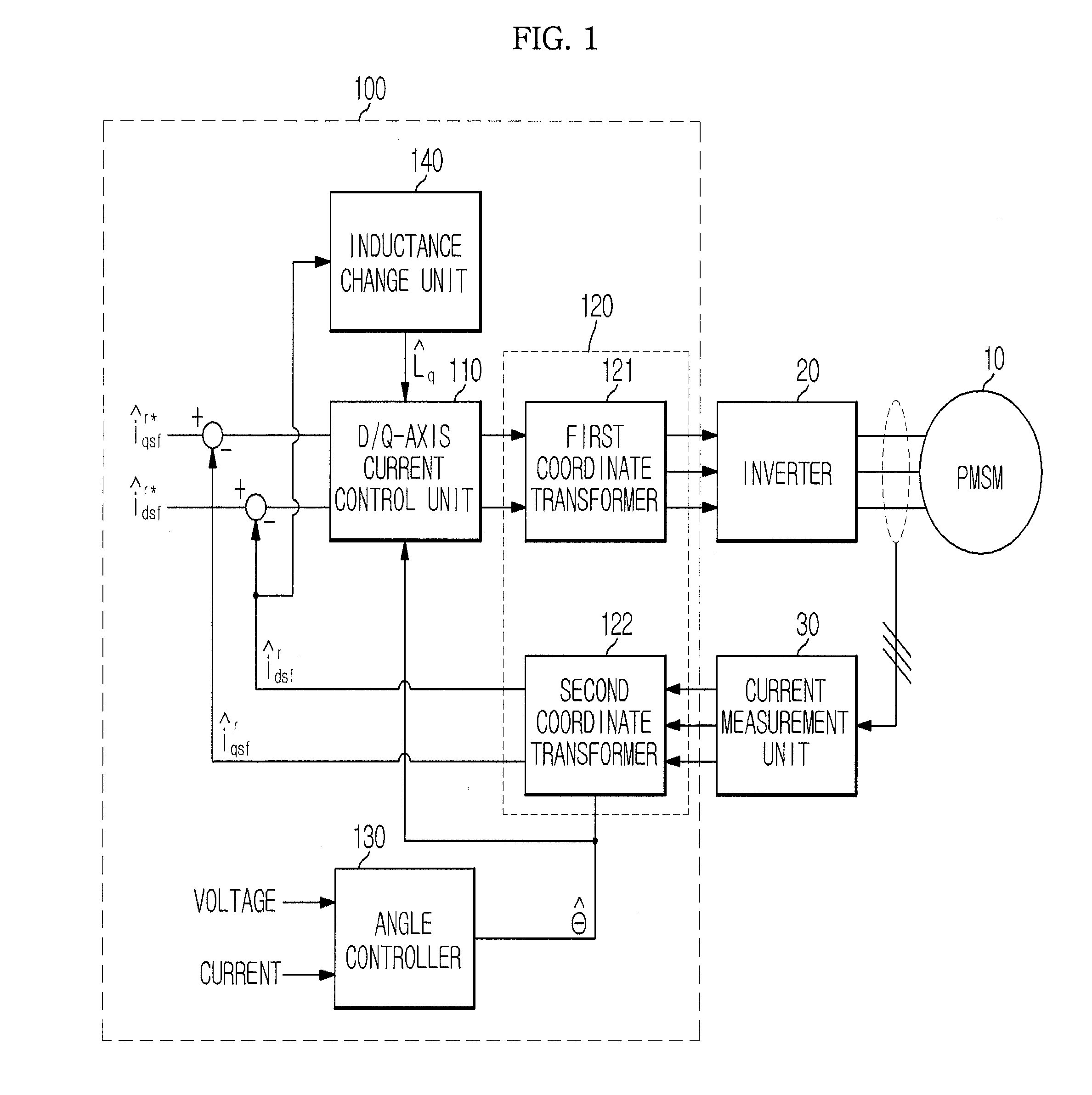
[0011]Therefore, it is an aspect of the present disclosure to provide an apparatus and method of estimating inductance of a permanent magnet synchronous motor (PMSM) which more accurately and reliably estimates inductance from among parameters of the PMSM.

Problems solved by technology

Vector control has a high requirement of a position sensor to acquire a reference magnetic flux, but the position sensor has low reliability under the condition of a compressor which is sealed and raised to a high temperature and cost rise due to installation of the position sensor provides a burden to a manufacturer.
However, the designed values differ from actual parameters due to environmental variation, i.e., change of natural phenomena which are relatively monotonously raised or lowered for a long time, manufacturing tolerance and operating environmental variation.
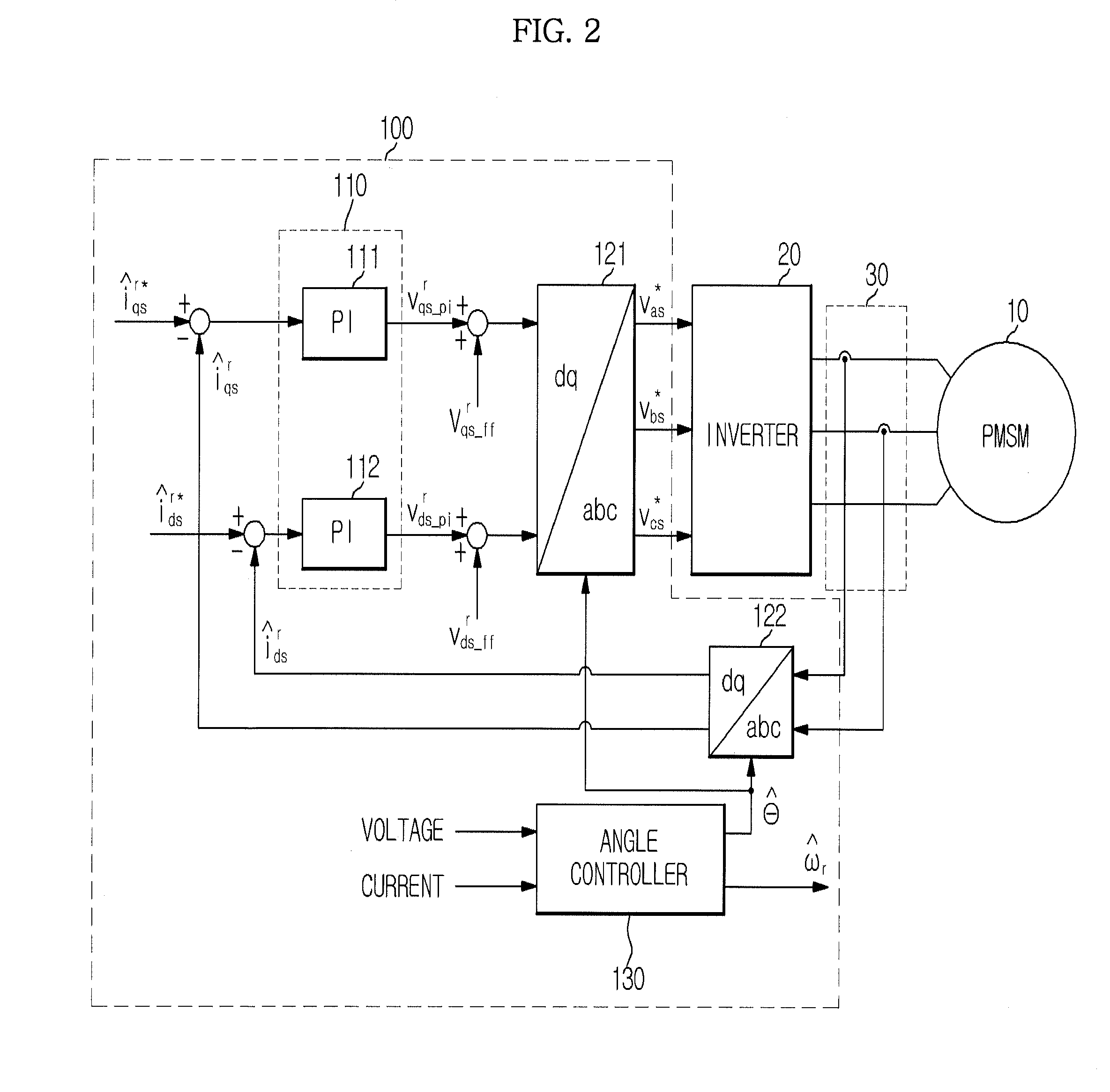
In the sensorless technique using a voltage equation, parameters of the motor are used during a process of detecting the position of the magnetic flux of a rotor, and thus errors of the parameters of the motor used in sensorless control affect position estimation performance.
That is, the errors in the parameters may lower control performance of the motor, and thus acquisition of correct parameters is important in sensorless operation.
However, the position of the d-axis estimated through sensorless control under the condition that the correct parameters are not known, and position error of the d-axis is reflected in current error during d / q-axis conversion of phase current process and thus acts as error in estimating the parameters using the voltage equation.

Method used


Image

  • Apparatus and method of estimating inductance of permanent magnet synchronous motor
  • Apparatus and method of estimating inductance of permanent magnet synchronous motor
  • Apparatus and method of estimating inductance of permanent magnet synchronous motor

Examples


Embodiment Construction

[0039]Reference will now be made in detail to embodiments of the present disclosure, examples of which are illustrated in the accompanying drawings, wherein like reference numerals refer to like elements throughout.

[0040]In general, a position sensorless technique is classified into two types, i.e., a position sensorless method using saliency in which inductance of a winding is varied according to rotating position and a position sensorless method using back EMF in a winding of a motor.

[0041]The position sensorless method using back EMF is disadvantages in that back EMF is not generated or a magnitude of back EMF is small when a motor is stopped or operated at a low velocity and thus position estimation is difficult, but is advantageous in that the position sensorless method using back EMF is easily applied to both a motor with saliency and a motor without saliency when the motor is operated at a middle velocity or a high velocity.

[0042]Permanent magnet synchronous motors (PMSMs) ar...


PUM


Abstract

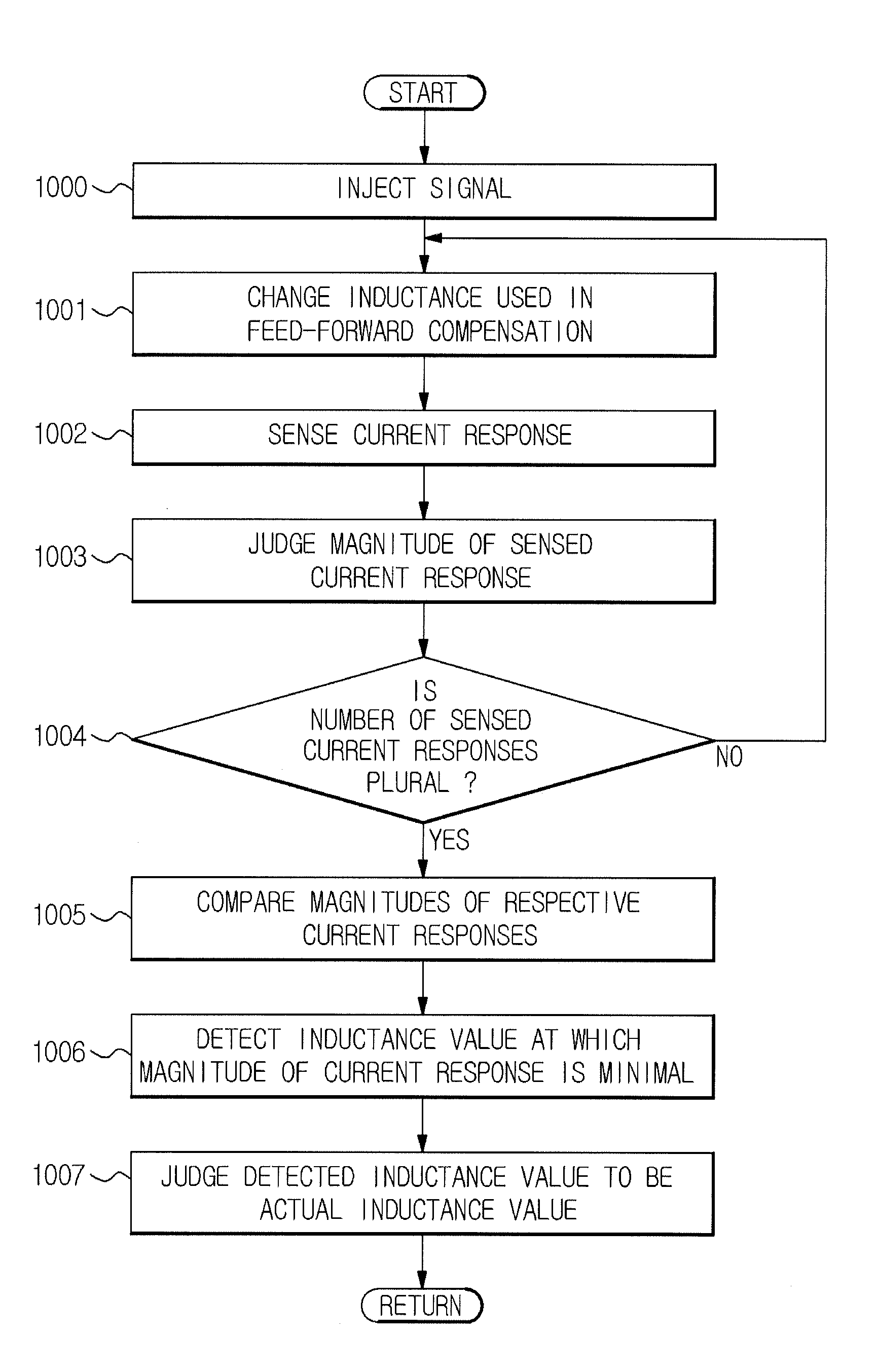
A method of estimating inductance of a permanent magnet synchronous motor (PMSM) includes injecting a signal having a frequency differing from an operating frequency of the PMSM into the PMSM during sensorless operation, sensing magnitudes of current responses to the injected signal, and estimating an inductance value at which the magnitude of the sensed current response is minimal to be an actual inductance value of the PMSM, thereby estimating inductance used in the PMSM regardless of position estimation error of the PMSM and thus more accurately and reliably estimating inductance of the PMSM.

Description

CROSS-REFERENCE TO RELATED APPLICATIONS[0001]This application claims the benefit of Korean Patent Application No. 2011-0009973, filed on Feb. 1, 2011 in the Korean Intellectual Property Office, the disclosure of which is incorporated herein by reference.BACKGROUND[0002]1. Field[0003]Embodiments of the present disclosure relate to an apparatus and method of estimating inductance of a permanent magnet synchronous motor (PMSM) which estimates parameters of the PMSM during sensorless operation.[0004]2. Description of the Related Art[0005]Most air conditioning apparatuses sold for home or industrial use employ electric motors to compress a refrigerant. Recently, a permanent magnet synchronous motor (PMSM) having excellent energy efficiency and output density has been proposed as an electric motor to drive a compressor in an air conditioning apparatus.[0006]In order to effectively operate the PMSM, a vector control technique based on magnetic flux may be applied. Vector control has a high...

Claims


Application Information

Patent Timeline
Patent Type & Authority Patents(United States)
IPC IPC(8): H02P6/18
CPCH02P6/18G01R27/08G01R27/2611G01R31/343
Inventor LEE, DONG HWANPARK, YOUNG JAEPARK, YONG SOONSUL, SEUNG KI
Owner SAMSUNG ELECTRONICS CO LTD
Learn More