Circuits, apparatuses, and methods for delay models

a delay model and circuit technology, applied in the field of integrated circuits, can solve the problems of large amount of power consumption, low power delay models are typically not as accurate as models, and low power delay models may not be as accura

Active Publication Date: 2014-08-05
MICRON TECH INC
View PDF4 Cites 2 Cited by
  • Summary
  • Abstract
  • Description
  • Claims
  • Application Information

AI Technical Summary

Problems solved by technology

Accurate delay models, however, typically consume large amounts of power, which can be disadvantageous due to the cost of and heat generated by such power consumption.
However, these low power delay models are typically not as accurate as a model that uses, for example, full size gates and wires that identically match the actual signal path.
These low power delay models may not be as accurate due to the fact that, for example, process, temperature, and voltage variations affect a smaller size inverter differently than a much larger inverter.
However, this type of adjustment is generally static and cannot be changed once the circuit is manufactured.
Hence, if the temperature or voltage of the circuit changes during operation and does not match the parameters used to statically adjust the low power delay model, these dynamic changes will cause the low power delay model to be less accurate due to the disparate effect the temperature and voltage variations have on the low power model as compared with the path being modeled.
Similarly, if the process used to manufacture the low power and / or the modeled path is slightly different than expected, the low power delay model may not correctly model the signal path.

Method used


Image

  • Circuits, apparatuses, and methods for delay models
  • Circuits, apparatuses, and methods for delay models
  • Circuits, apparatuses, and methods for delay models

Examples


Embodiment Construction

[0014]Certain details are set forth below to provide a sufficient understanding of embodiments of the invention. However, it will be clear to one skilled in the art that embodiments of the invention may be practiced without these particular details. Moreover, the particular embodiments of the present invention described herein are provided by way of example and should not be used to limit the scope of the invention to these particular embodiments. In other instances, well-known circuits, control signals, timing protocols, and software operations have not been shown in detail in order to avoid unnecessarily obscuring the invention.

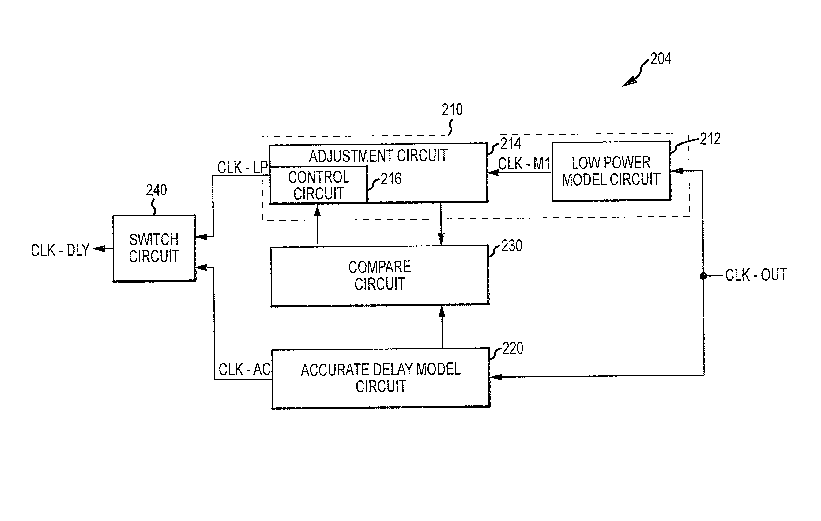
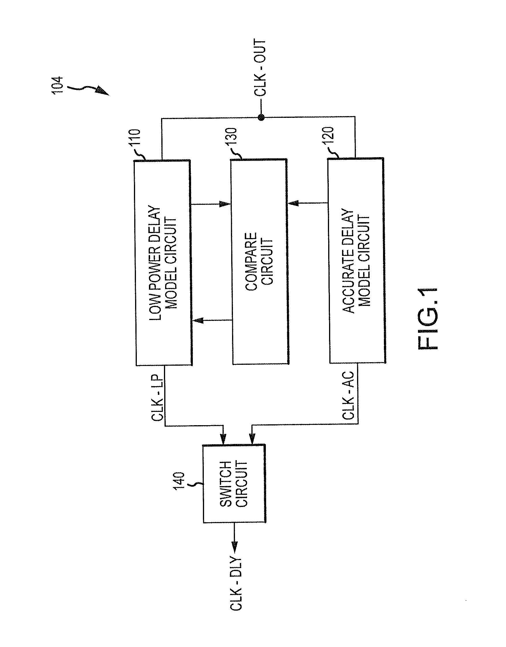
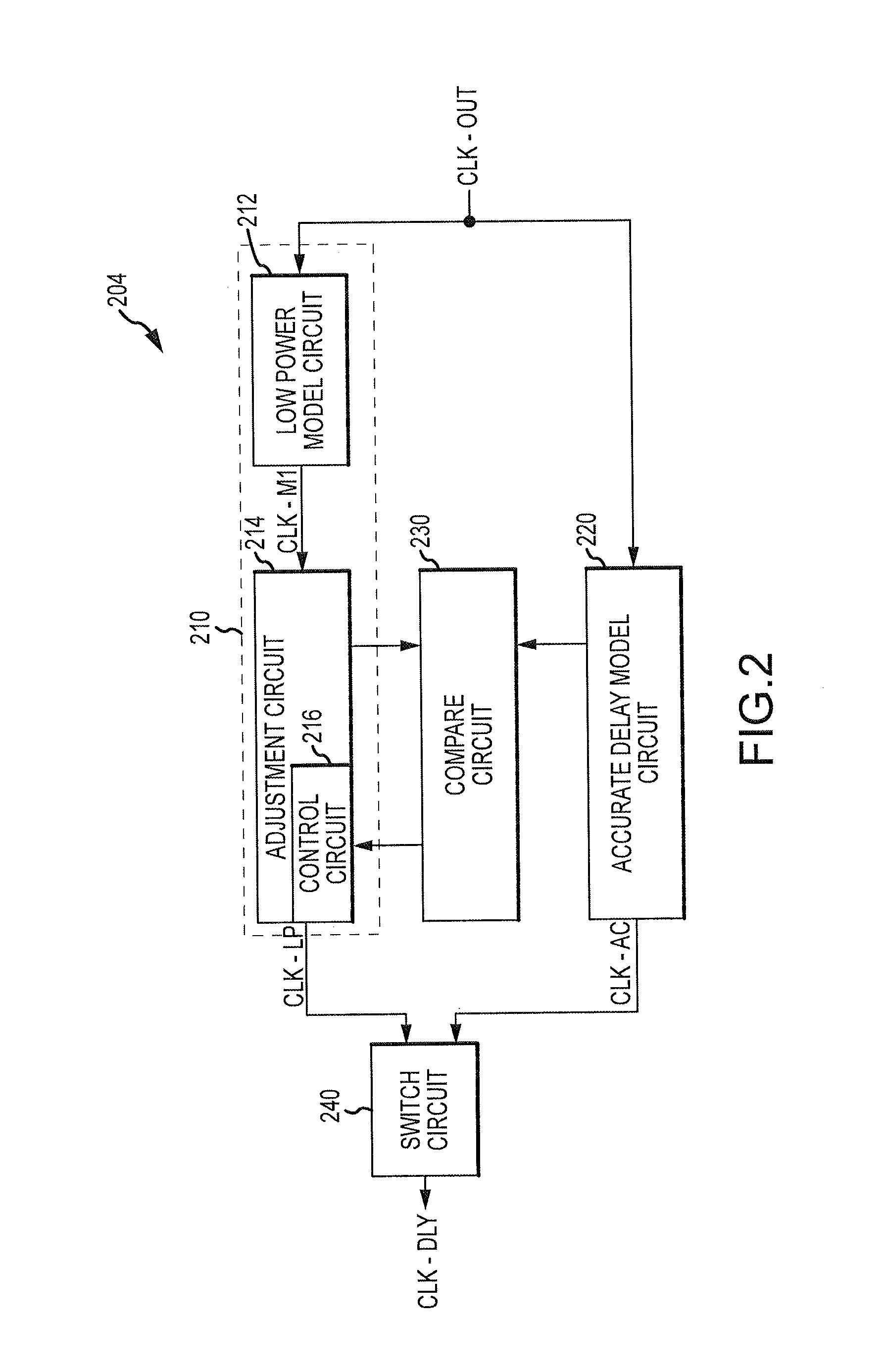
[0015]FIG. 1 illustrates an apparatus including delay model circuit 104 according to an embodiment of the invention. As used herein, apparatus may refer to, for example, an integrated circuit, a memory device, a memory system, an electronic device or system, a smart phone, a tablet, a computer, a server, etc. The delay model circuit 104 includes a first, ac...


PUM


Abstract

Circuits, apparatuses, and methods are disclosed for delay models. In one such example circuit, a first delay model circuit is configured to provide a first output signal by modeling a delay of a signal through a path. A second delay model circuit is configured to provide a second output signal by modeling the delay of the signal through the path. A compare circuit is coupled to the first and second delay model circuits. The compare circuit is configured to compare a third signal from the first delay model circuit and a fourth signal from the second delay model circuit, and, in response provide an adjustment signal to adjust the delay of the second delay model circuit.

Description

TECHNICAL FIELD[0001]Embodiments of the invention relate generally to integrated circuits, and more particularly, in one or more of the illustrated embodiments, to delay models.BACKGROUND OF THE INVENTION[0002]Frequently in integrated circuits, there is a need to model the delay of a signal through a particular path so that, for example, the delay can be matched. As just one example, in a delay-locked loop (DLL), a feedback delay model circuit models the delay of a clock signal through an input and / or an output stage of the DLL. This modeled delay is then used to calibrate the DLL in order to for it to lock an output clock signal with an external clock signal by compensating for the modeled delay. Generally, the more accurate the delay model, the more accurate the DLL and the DLL lock will be, and so it can be advantageous to have a relatively accurate delay model.[0003]Accurate delay models, however, typically consume large amounts of power, which can be disadvantageous due to the ...

Claims


Application Information

Patent Timeline
Patent Type & Authority Patents(United States)
IPC IPC(8): H03H11/26
CPCH03L7/0816G11C7/22H03L7/08H03L7/097H03K5/159G11C7/222H03L7/0802G11C7/04
Inventor BRINGIVIJAYARAGHAVAN, VENKATRAGHAVANBROWN, JASONGOMM, TYLER J.
Owner MICRON TECH INC
Why Eureka
Try Eureka