Radio wave transmitting decorative member and the production method thereof

a technology of decorative elements and radio waves, applied in protective material radiating elements, instruments, vacuum evaporation coatings, etc., can solve the problems of low production efficiency, low cost, and tin oxidation, and achieve low cost, efficient and stable production, and low cost

Active Publication Date: 2014-08-26
SHIN-ETSU POLYMER CO LTD
View PDF27 Cites 15 Cited by
  • Summary
  • Abstract
  • Description
  • Claims
  • Application Information

AI Technical Summary

Benefits of technology

[0038]The radio wave transmitting decorative member of the present invention is provided with radio wave transmitting properties as well as mirror-surface like metallic luster, hardly loses its metallic luster, and can be produced at a low cost.
[0039]The method of producing the radio wave transmitting decorative member of the present invention provides efficient and stable production of the radio wave transmitting decorative member having radio wave transmitting properties as well as mirror-surface like metallic luster, hardly loses its metallic luster, and can be produced at a low cost.

Problems solved by technology

(iv) The frequency of radio waves used in the communication devices (Wireless PAN such as Bluetooth, UWB, ZigBee or the like) has been shifting to a high frequency range, at which radio waves are readily affected by the decorative members, and thus these devices are prone to functional disorders.
In addition, tin is prone to oxidation, chlorination, or the like, as a result of which the metallic luster thereof is lost over time.
On the other hand, indium is highly expensive.
On the other hand, with respect to the above decorative member of (4), only radio waves having a specific frequency that conforms to the size of the opening of the light reflecting layer can pass therethrough, therefore, the use of the decorative member of (4) is limited due to the specific frequency.

Method used


Image

  • Radio wave transmitting decorative member and the production method thereof
  • Radio wave transmitting decorative member and the production method thereof
  • Radio wave transmitting decorative member and the production method thereof

Examples


first embodiment

The First Embodiment

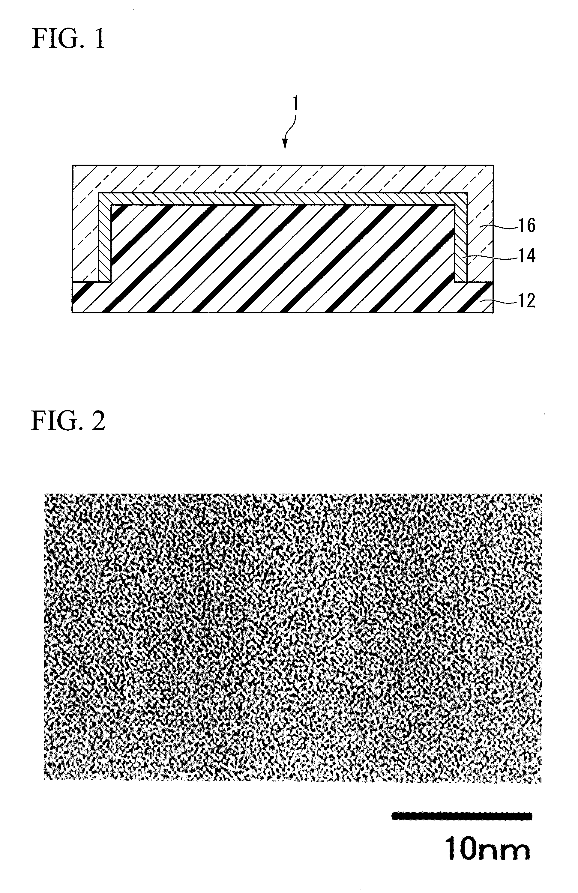
[0055]FIG. 1 is a cross sectional view showing an example of a radio wave transmitting decorative member of the present invention.

[0056]A radio wave transmitting decorative member 1 includes a substrate 12 having a convex side; a transparent organic material layer 16 having a concave side and a light reflecting layer 14, wherein the light reflecting layer 14 is placed in the concave side of the transparent organic material layer 16; wherein the radio wave transmitting decorative member 1 is integrated by incorporating the convex side and the concave side.

(Substrate)

[0057]A substrate 12 is a shaped article of a radio wave transmitting material.

[0058]Examples of radio wave transmitting materials include insulating substrates made of an insulating organic or inorganic material. The term “insulating” means a surface resistivity of 106Ω or higher, and the surface resistivity is preferably 108Ω or higher. The surface resistivity of a substrate is measured by a four-pin...

second embodiment

The Second Embodiment

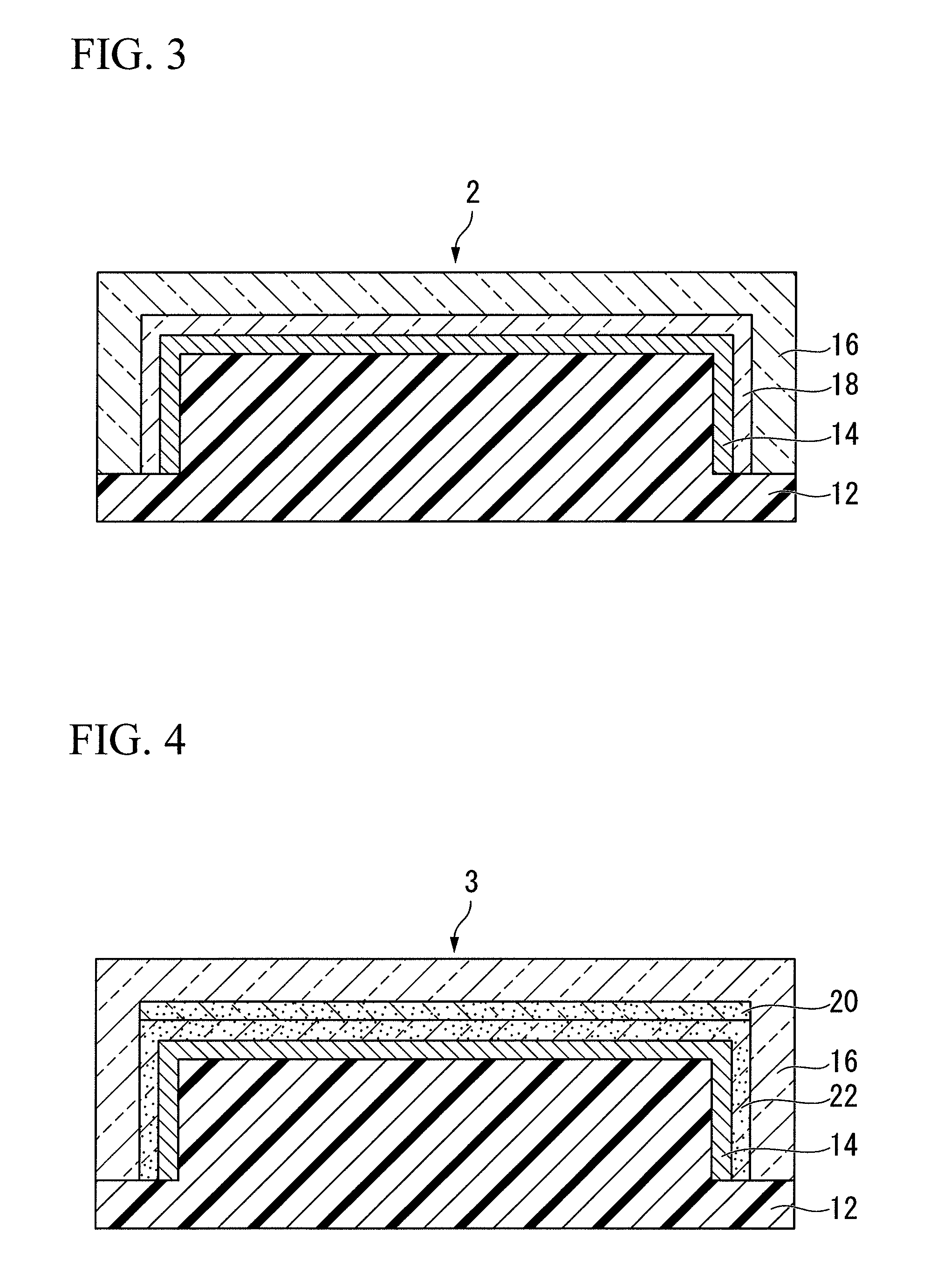
[0098]FIG. 3 is a cross sectional view showing another example of a radio wave transmitting decorative member according to the present invention.

[0099]A radio wave transmitting decorative member 2 includes a substrate 12 having a convex side; a transparent organic material layer 16 having a concave side which corresponds to the convex side, a low refractive index layer 18 placed in the concave side, and further a light reflecting layer 14 placed on the surface of the low refractive index layer 18; wherein the radio wave transmitting decorative member 2 is integrated by incorporating the convex side and the concave side.

[0100]Since the reference number in Embodiment 2 is the same as the one represented in Embodiment 1, explanations of the reference numbers which have already been described will be omitted.

(A Low Refractive Index Layer)

[0101]A low refractive index layer 18 is lower in refractive index than that of the transparent organic material layer 16.

[0102]Th...

third embodiment

The Third Embodiment

[0109]FIG. 4 is a cross sectional view showing another example of a radio wave transmitting decorative member of the present invention.

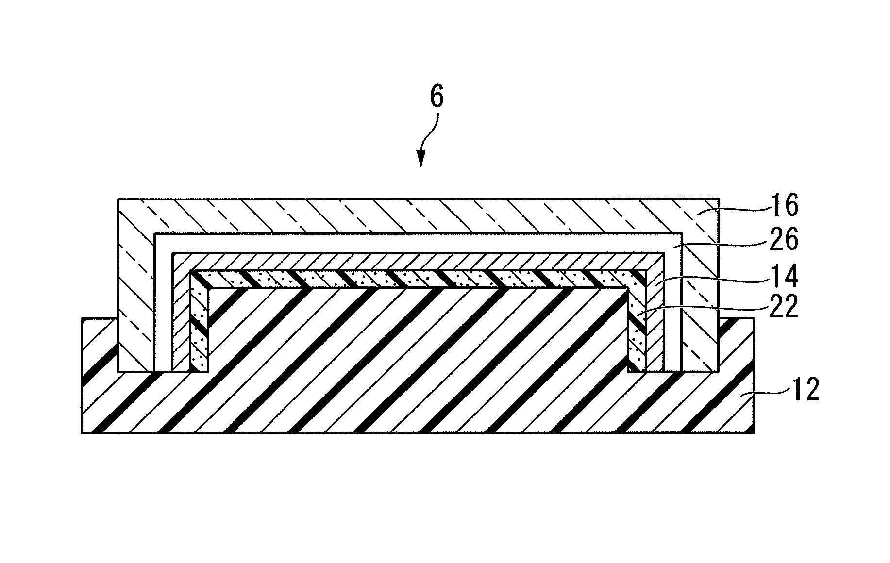
[0110]A radio wave transmitting decorative member 3 includes a substrate 12 having a convex side; a transparent organic material layer 16 having a concave side corresponding to the convex side, a transparent colored layer 20 placed on the bottom of the concave side, further an adhesion promoting layer 22 placed on the surface of the transparent colored layer 20, and further a light reflecting layer 14 placed on the surface of the adhesion promoting layer 22; wherein the radio wave transmitting decorative member 3 is integrated by incorporating the convex side and the concave side.

[0111]Since the reference number in Embodiment 3 is the same as the one represented in Embodiment 1, explanations of the reference numbers which have already been described will be omitted.

(Colored Layer)

[0112]A transparent colored layer 20 is placed betw...


PUM

PropertyMeasurementUnit
reflectanceaaaaaaaaaa
particle diameteraaaaaaaaaa
frequencyaaaaaaaaaa

Abstract

The radio wave transmitting decorative member and the method of producing thereof efficiently and stably of the present invention is provided with radio wave transmitting properties as well as mirror-surface like metallic luster, hardly loses its metallic luster, and can be produced at a low cost. The method of producing a radio wave transmitting decorative member, having a substrate, a transparent organic material layer, and a light reflecting layer formed of an alloy composed of either silicon or germanium and a metal provided between the substrate and the transparent organic material layer; wherein the light reflecting layer is formed from a target having an alloy composed of either silicon or germanium, and of a metal with the use of a DC magnetrons sputtering.

Description

CROSS-REFERENCE TO RELATED APPLICATIONS[0001]The present application is a 35 U.S.C. §§371 national phase conversion of PCT / JP2010 / 000270, filed Jan. 19, 2010, which claims priority of Japanese Patent Application Nos. 2009-010378 and 2009-061136, filed Jan. 20, 2009 and Mar. 13, 2009, respectively, the contents of which are incorporated herein by reference. The PCT International Application was published in the Japanese language.TECHNICAL FIELD[0002]The present invention relates to a radio wave transmitting decorative member having metallic luster and the production method thereof.BACKGROUND OF THE ART[0003]From the viewpoint of design properties, metallic decorative members, in particular, decorative members having mirror-surface like metallic luster have been widely used in the casing or buttons of mobile phones; the casing of watches; and the front grille, bumper or the like of a vehicle.[0004]As such decorative members, a decorative member that transmits radio waves (microwaves o...

Claims


Application Information

Patent Timeline
Patent Type & Authority Patents(United States)
IPC IPC(8): H01Q1/36
CPCC23C14/0015C23C14/20C23C14/35H01Q1/243H01Q1/3233H01Q1/422H01Q1/44H01Q1/42
Inventor KAWAGUCHI, TOSHIYUKITAHARA, KAZUTOKISAGA, TSUTOMU
Owner SHIN-ETSU POLYMER CO LTD
Why Eureka
Try Eureka