Light emitting device

a light-emitting device and light-emitting technology, which is applied in the field of light-emitting devices, can solve the problems of color difference in different light-emitting devices, parts of lights, and increased chromaticity difference of mixed-color light, so as to reduce optical loss, reduce chromaticity variation of lights, and reduce optical loss

Active Publication Date: 2014-09-02
PANASONIC CORP
View PDF9 Cites 0 Cited by
  • Summary
  • Abstract
  • Description
  • Claims
  • Application Information

AI Technical Summary

Benefits of technology

[0005]In view of the above, the present invention provides a light emitting device capable of reducing a chromaticity variation in the light of mixed color and improving a light emission efficiency.
[0008]In accordance with the embodiment of the present invention, the light emitting device includes the red and the green light emitting unit respectively formed by coating the red and the green coating member on the LED unit emitting a white light. Accordingly, it is possible to reduce the chromaticity variations of lights emitted from the red and the green light emitting units. Thus, it is possible to reduce a chromaticity variation of the light obtained by mixing lights emitted from the red, the green and the white light emitting unit. In addition, since the white light emitting unit uses the LED unit emitting a white light as it is, it is possible to reduce an optical loss caused by the coating member or the like and improve emission efficiency of the light emitting device.

Problems solved by technology

In these types of light emitting devices, when a chromaticity variation range of each LED light source is large, a chromaticity difference of the light of mixed color is also increased, which may cause the color difference in different light emitting devices.
However, in the lighting device described in JP4286935B, lights of various colors other than the white color are first converted into a white light, and thus parts of the lights are lost during the conversion, which may lower light emission efficiency.
In particular, when emitting a light with a light emission spectrum significantly different from that of the white light, it is necessary to increase a concentration of a fluorescent material contained in the resin cap for conversion into the white color, which may greatly degrade light emission efficiency.
In addition, in case of emitting a light of the white color by combination of three-color RGB LEDs, and then further converting the produced white color light into a light of different color, the color conversion is carried out twice, resulting in the increased loss of optical energy.

Method used


Image

  • Light emitting device
  • Light emitting device
  • Light emitting device

Examples


Embodiment Construction

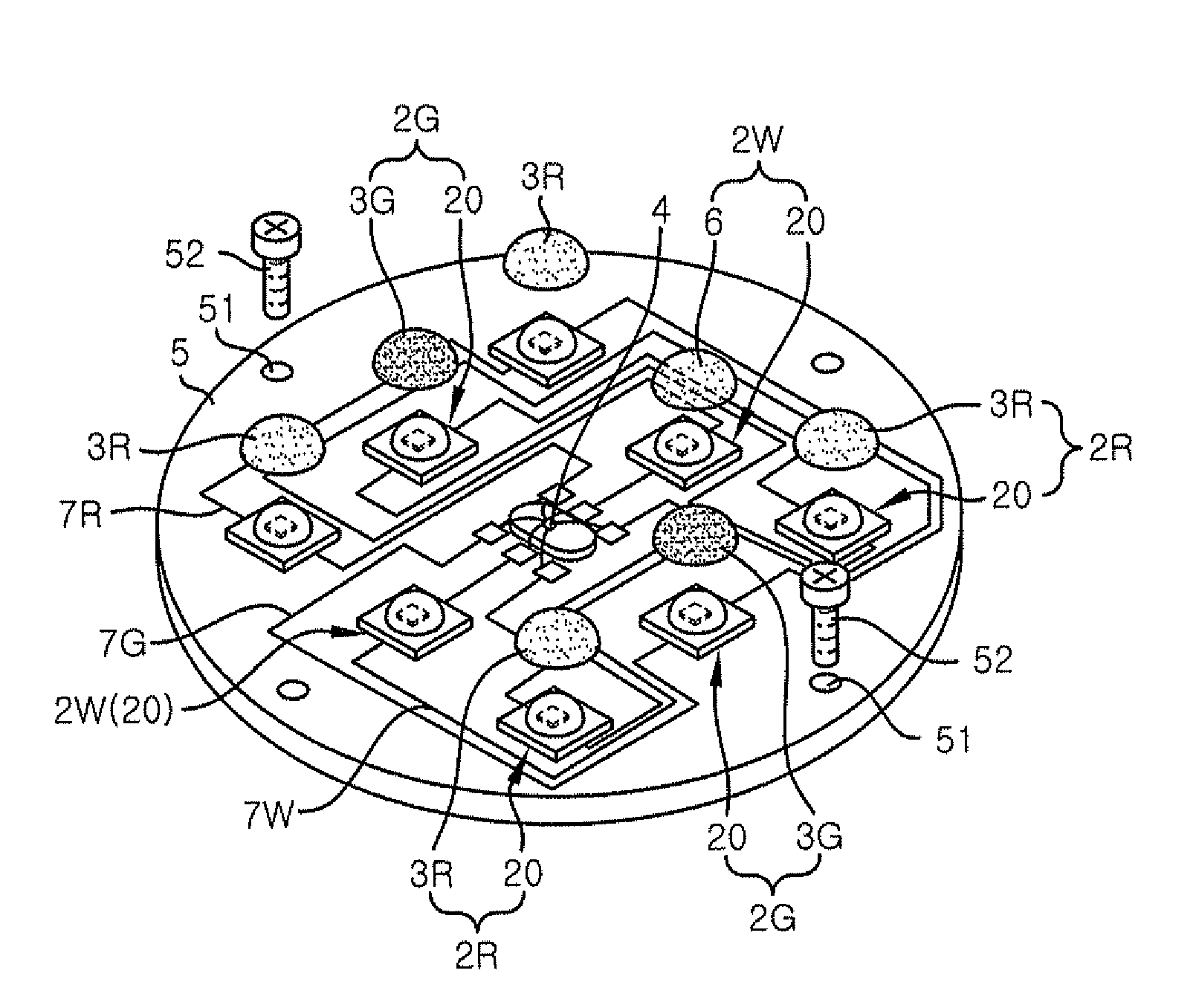
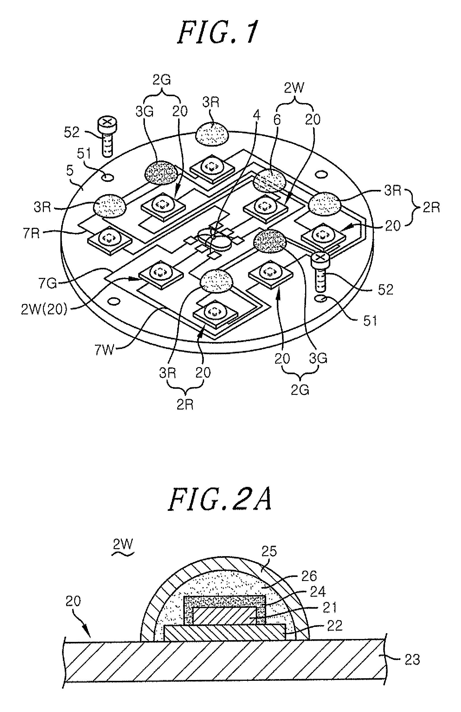
[0016]Hereinafter, a light emitting device 1 in accordance with an embodiment of the present invention will be described with referent to FIGS. 1 to 6 which form a part hereof. The light emitting device 1 includes a plurality of light emitting units 2 which emit lights of different color. A light emitting diode (LED) unit 20 which emits a white light is used as a light source of each of the light emitting units 2. The light emitting units 2, as shown in FIG. 1, include white light emitting units 2W for emitting white lights, red light emitting units 2R for emitting red lights, and green light emitting units 2G for emitting green lights, each having one LED unit 20.

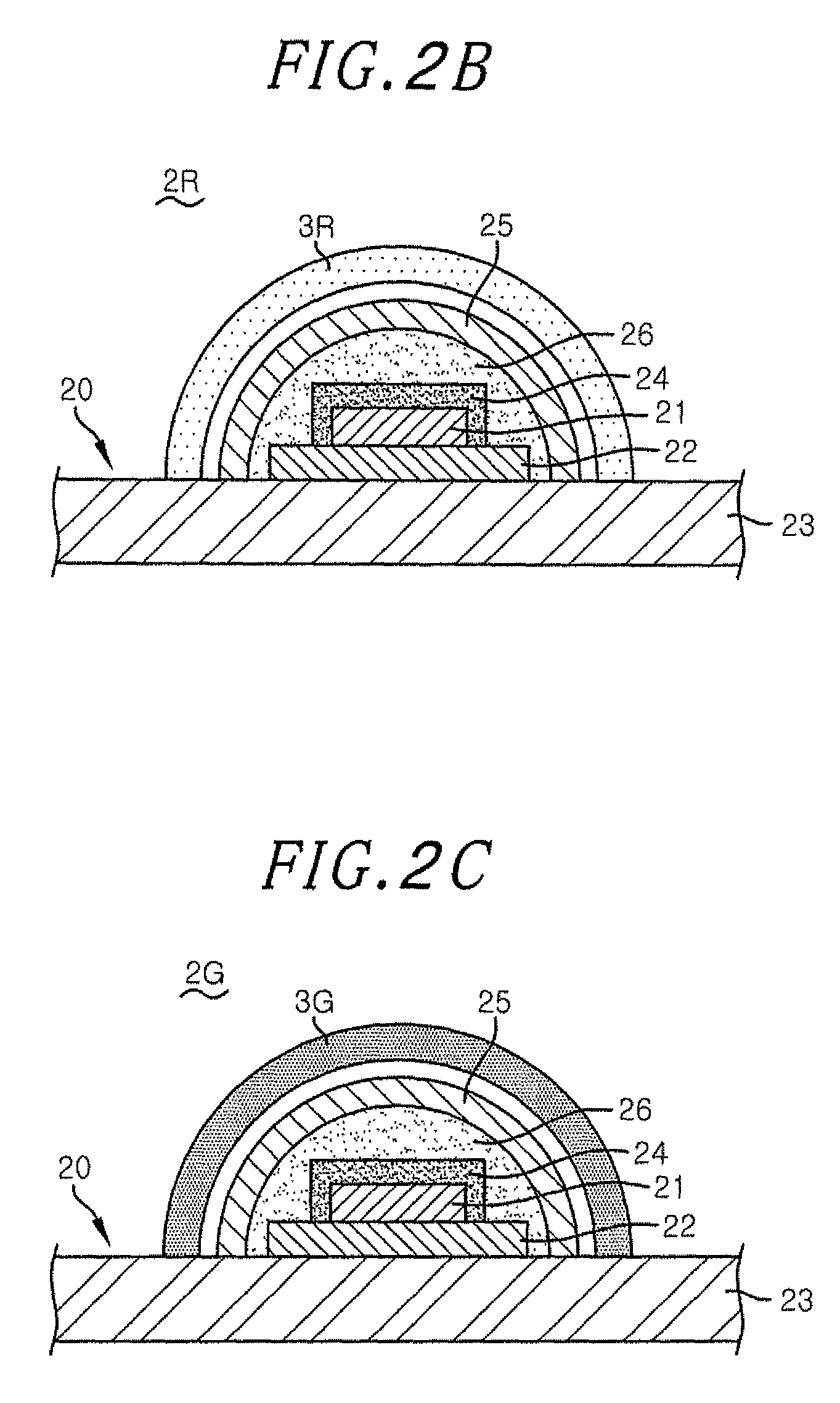
[0017]Each of the red light emitting units 2R further includes a red coating member 3R having a red fluorescent material converting the light emitted from the LED unit 20 into a red light. Each of the green light emitting units 2G further includes a green coating member 3G having a green fluorescent material converting the...


PUM


Abstract

A light emitting device includes a white light emitting unit including a first light source emitting a white light; a red light emitting unit including a second light source emitting a white light and a red coating member having a red fluorescent material which converts the white light from the second light source into a red light; and a green light emitting unit including a third light source emitting a white light and a green coating member having a green fluorescent material which converts the white light from the third light source into a green light. The light emitting device further includes a driver for individually driving the white, the red and the green light emitting unit.

Description

FIELD OF THE INVENTION[0001]The present invention relates to a light emitting device including a plurality of solid light emitting sources.BACKGROUND OF THE INVENTION[0002]A light emitting diode (LED) emits a light having high brightness with low power consumption and thus has been used as a light source of various electric devices such as a display, a lighting device and the like. Recently, as a blue LED has been commercialized in addition to a red LED and a green LED, those LEDs of three RGB colors have been combined to create lights of various colors. Also, there is proposed a light emitting device employing such LED light sources emitting lights of different colors, and complementarily controlling light amounts thereof to thereby adjust chromaticity of a light of mixed color.[0003]In these types of light emitting devices, when a chromaticity variation range of each LED light source is large, a chromaticity difference of the light of mixed color is also increased, which may cause...

Claims


Application Information

Patent Timeline
Patent Type & Authority Patents(United States)
IPC IPC(8): F21Y105/00H01L25/075H05B33/08F21Y101/02H01L33/50F21Y113/00F21V23/00F21K99/00H01L27/15H05B44/00
CPCH05B33/0857F21Y2101/02F21Y2113/005H01L2924/0002F21K9/00F21V23/005H01L33/504H01L25/0753F21Y2105/001F21Y2105/10F21Y2115/10F21Y2113/13H05B45/20H01L2924/00
Inventor YAMAMOTO, YUYA
Owner PANASONIC CORP
Why Eureka
Try Eureka