Manufacturing method for light emitting device and phosphor mixture

a manufacturing method and technology of phosphor, which are applied in the field of manufacturing methods of light emitting devices and phosphor mixtures, can solve the problems of phosphor not being collected or reused, sealing agent may deteriorate by heat generated by light emitting elements, etc., and achieve the reduction of chromaticity variation of manufactured light emitting devices, the effect of increasing the strength of phosphor layers

Inactive Publication Date: 2016-02-16
KONICA MINOLTA INC
View PDF21 Cites 0 Cited by
  • Summary
  • Abstract
  • Description
  • Claims
  • Application Information

AI Technical Summary

Benefits of technology

[0025]According to the present invention, particular plate-like particles are contained in the first liquid mixture or the phosphor mixture, so that the strength of phosphor layers is increased and separation of the phosphor layers can be prevented, and by extension, the chromaticity variation of manufactured light emitting devices can be reduced.

Problems solved by technology

Therefore, when phosphor is provided directly on a light emitting element in such a way as to be dispersed in a sealing agent as described above, the sealing agent may deteriorate by heat generated by the light emitting element.
Hence, it is difficult to make phosphor evenly exist on a light emitting element, so that released white light is uneven, and accordingly chromaticity varies between light emitting devices.
However, in the technique by which polyhydric alcohol is used as a solvent of an application liquid in which phosphor is dispersed in a ceramic precursor solution, the phosphor adhering onto a mask component was covered with ceramics formed by the ceramic precursor solution and accordingly fixed onto the mask component, so that the phosphor was not able to be collected or reused.

Method used


Image

  • Manufacturing method for light emitting device and phosphor mixture
  • Manufacturing method for light emitting device and phosphor mixture
  • Manufacturing method for light emitting device and phosphor mixture

Examples


example 1

(2.4) Example 1

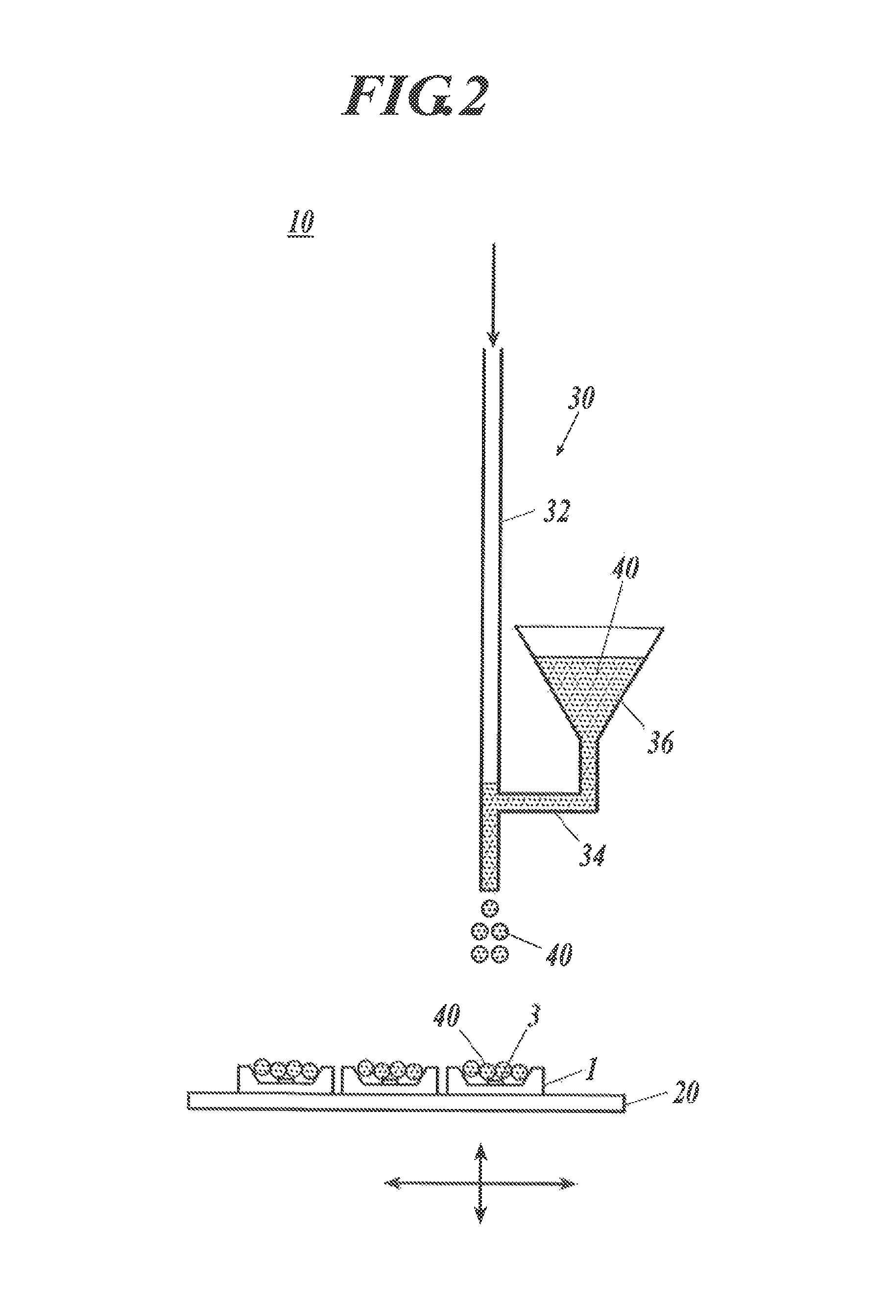
[0139]The first liquid mixture was produced by mixing 0.04 g of synthetic mica (MICROMICA MK-100 with an average particle size of 4 μm manufactured by Co-op Chemical Co., Ltd.) and 0.81 g of the phosphor into 1 g of propylene glycol. This first liquid mixture was sprayed to be applied onto the LED devices by using the application device shown in FIG. 2 and dried for one hour at 50° C., whereby phosphor layers were formed.

[0140]After that, from above the phosphor layers, a polysiloxane dispersion liquid (14 mass % of polysiloxane and 86 mass % of IPA) was sprayed to be applied thereto as the second liquid mixture and fired for one hour at 150° C., whereby the phosphor of the phosphor layers was fixed, and wavelength converting parts were formed.

[0141]The spray application condition was the same as that of the comparative example 3.

example 2

(2.5) Example 2

[0142]The first liquid mixture was produced by mixing 0.04 g of inorganic particles (RX300 with a particle size of 7 nm manufactured by Nippon. Aerosil Co., Ltd.), 0.04 g of smectite (LUCENTITE SWN with an average particle size of 50 nm manufactured by Co-op Chemical Co., Ltd.) and 0.77 g of the phosphor into 1 g of ethylene glycol. This first liquid mixture was sprayed to be applied onto the LED devices by using the application device shown in FIG. 2 and dried for one hour at 50° C., whereby phosphor layers were formed.

[0143]After that, from above the phosphor layers, a polysiloxane dispersion liquid (14 mass % of polysiloxane and 86 mass % of IPA) was sprayed to be applied thereto as the second liquid mixture and fired for one hour at 150° C., whereby the phosphor of the phosphor layers was fixed, and wavelength converting parts were formed.

[0144]As to the spray application condition, the application speed of the first liquid mixture was 50 mm / s, the spray pressure ...

example 3

(2.6) Example 3

[0145]The first liquid mixture was produced, by mixing 0.065 g of inorganic particles (RX300 with a particle size of 7 nm manufactured by Nippon Aerosil Co., Ltd.), 0.025 g of smectite (LUCENTITE SWN with an a verage particle size of 50 nm manufactured by Co-op Chemical Co., Ltd.) and 1 g of the phosphor into 1 g of propylene glycol and 0.75 g of isopropyl alcohol. This first liquid mixture was sprayed to be applied onto the LED devices by using the application device shown in FIG. 2 and dried for one hour at 50° C., whereby phosphor layers were formed.

[0146]After that, from above the phosphor layers, a polysiloxane dispersion liquid (14 mass % of polysiloxane and 86 mass % of IPA) was sprayed to be applied thereto as the second liquid mixture and fired for one hour at 150° C., whereby the phosphor of the phosphor layers was fixed, and wavelength converting parts were formed.

[0147]The spray application condition was the same as that of the example 2.


PUM

PropertyMeasurementUnit
aspect ratioaaaaaaaaaa
boiling pointaaaaaaaaaa

Abstract

Disclosed is a manufacturing method for a light emitting device including a light emitting element and a wavelength converting part which converts light emitted from the light emitting element into light of another wavelength. The manufacturing method includes a first step and a second step. The first step is a step of applying onto the light emitting element and drying a first liquid mixture in which phosphor and plate-like particles are dispersed in polyhydric alcohol having a valence of two or more to form a phosphor layer. The second step is a step of applying onto the phosphor layer and firing a second liquid mixture in which a translucent ceramic precursor is dispersed in a solvent to form the wavelength converting part.

Description

CROSS-REFERENCE TO RELATED APPLICATIONS[0001]This application is a 371 of PCT / JP2012 / 053578 filed on Feb. 15, 2012, which dams the priority of Japanese Application Serial No. 2011-053766 filed on Mar. 11, 2011, the contents of each of which are incorporated herein by reference.FIELD OF THE INVENTION[0002]The present invention relates to a manufacturing method for a light emitting device and a phosphor mixture which is suitably used in the manufacturing method.BACKGROUND OF THE ART[0003]Hitherto, there has been developed, to be used for an illuminator or the like a light emitting device which produces white light by making phosphor emit, light by using light emitted from a light emitting element such as an LED element as excitation light.[0004]As such a light emitting device, there is known, for example, a light emitting device which produces white light by using phosphor which emits yellow light through blue light emitted from a light emitting element and mixing the colors of light ...

Claims


Application Information

Patent Timeline
Patent Type & Authority Patents(United States)
IPC IPC(8): H01L33/50C08G77/50C09K11/02H01L33/26H05B33/10
CPCH01L33/26H01L33/501C09K11/025H05B33/10H01L2933/0041H01L2924/181H01L2224/16225H01L2924/00012
Inventor WASHIZU, TAKASHIHATANO, TAKUJITAGUCHI, YOSHIHITO
Owner KONICA MINOLTA INC
Why Eureka
Try Eureka