Manufacturing method of light emitting elements, and manufacturing apparatus of light emitting elements

a manufacturing apparatus and technology of light emitting elements, applied in the direction of electroluminescent light sources, semiconductor/solid-state device testing/measurement, coatings, etc., can solve the problems of lowering the yield, and achieve the effect of reducing the chromaticity variation of individual light emitting elements and lowering the light-extraction efficiency

Active Publication Date: 2015-12-22
PANASONIC INTELLECTUAL PROPERTY MANAGEMENT CO LTD
View PDF22 Cites 0 Cited by
  • Summary
  • Abstract
  • Description
  • Claims
  • Application Information

AI Technical Summary

Benefits of technology

[0051]By the present invention, can be furnished a manufacturing method of light emitting elements, and a manufacturing apparatus of light emitting elements such that it is possible to reduce the chromaticity variation of individual light emitting elements while avoiding a lowering of the light-extraction efficiency.

Problems solved by technology

Hence, the chromaticity variation of individual white-light emitting elements becomes a cause of a lowering of the yield.

Method used


Image

  • Manufacturing method of light emitting elements, and manufacturing apparatus of light emitting elements
  • Manufacturing method of light emitting elements, and manufacturing apparatus of light emitting elements
  • Manufacturing method of light emitting elements, and manufacturing apparatus of light emitting elements

Examples


embodiment 1

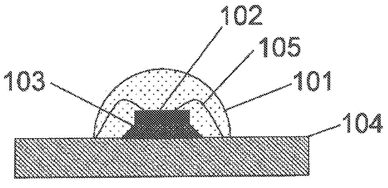
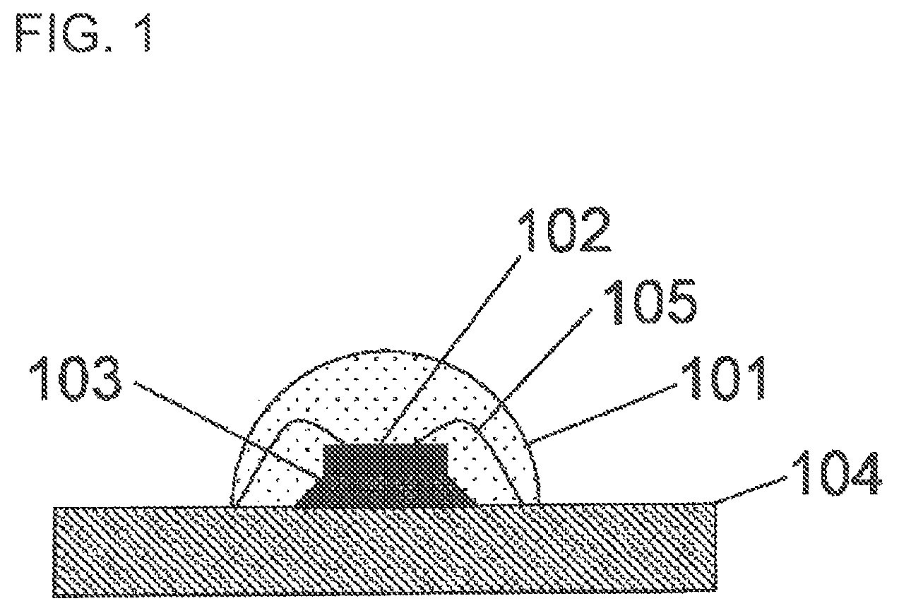
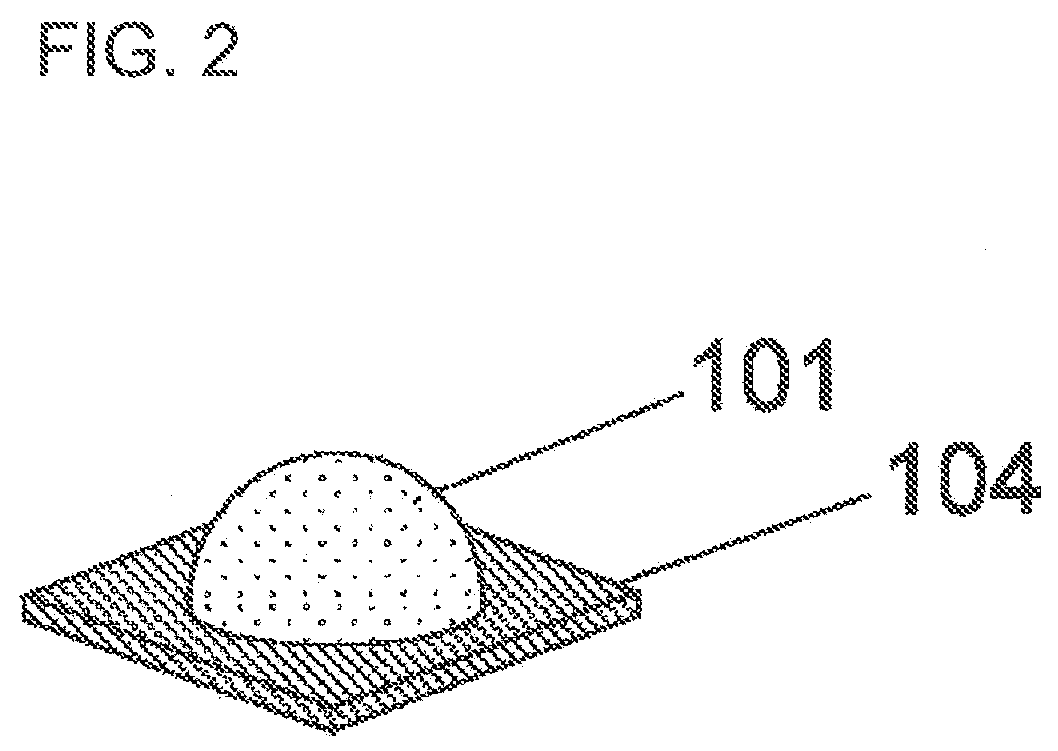
[0064]In the beginning, mainly referring to FIGS. 1 and 2, descriptions are given regarding the configuration of the white-light emitting element of the present embodiment.

[0065]Additionally, FIG. 1 is a schematic perpendicular-section view of the white-light emitting element of Embodiment 1 in the present invention.

[0066]Moreover, FIG. 2 is a schematic perspective view of the white-light emitting element of Embodiment 1 in the present invention.

[0067]The white-light emitting element of the present embodiment comprises the fluorescent-body-containing resin member 101, the light emitting diode chip 102, the die bond member 103, the base plate 104, and the gold (Au) wires 105.

[0068]The light emitting diode chip 102 is a blue-light emitting element such that the peak wavelength of its light emission is about 450 nm.

[0069]The fluorescent-body-containing resin member 101 is a member that has been formed with the fluorescent-body-containing resin material 202 (see FIG. 3(B)) as a mixture,...

embodiment 2

[0145]Next, mainly referring to FIG. 10, descriptions are given regarding the manufacturing method of white-light emitting elements of the present embodiment, and the configuration and action of the manufacturing apparatus of white-light emitting elements of the present embodiment.

[0146]Additionally, FIG. 10 is a schematic partial enlarged front view of the manufacturing apparatus of white-light emitting elements of Embodiment 2 in the present invention.

[0147]The manufacturing method of white-light emitting elements of the present embodiment is a manufacturing method of a white-light emitting element with the light emitting diode chip 102 (see FIG. 1) covered with the fluorescent-body-containing resin member 101 (see FIG. 1) that has been formed with the fluorescent-body-containing resin material 407 containing a resin and fluorescent bodies, and comprises: an irradiating step of irradiating the fluorescent-body-containing resin material 407 with the blue laser beam 201 (see FIG. 3(...


PUM


Abstract

A manufacturing method of white-light emitting elements that is one example of the present invention is a manufacturing method of a white-light emitting element with the light emitting diode chip covered with the fluorescent-body-containing resin member that has been formed with the fluorescent-body-containing resin material containing a resin and fluorescent bodies, and includes: an irradiating step of irradiating the fluorescent-body-containing resin material with the blue laser beam; a measuring step of measuring the fluorescence strength of the fluorescence light emission from the fluorescent bodies that have been excited by the blue laser beam with which the irradiation has been carried out; and an applying step of applying, to the light emitting diode chip, a quantity of the fluorescent-body-containing resin material, the quantity being based on the fluorescence strength that has been measured.

Description

CROSS-REFERENCE TO RELATED APPLICATIONS[0001]This application is a U.S. national phase application of PCT International Patent Application No. PCT / JP2012 / 001929 filed Mar. 21, 2012, claiming the benefit of priority of Japanese Patent Application No. 2011-115729 filed May 24, 2011, all of which are incorporated by reference herein in their entirety.TECHNICAL FIELD[0002]The present invention relates to a manufacturing method of light emitting elements, and a manufacturing apparatus of light emitting elements, for manufacturing light emitting elements that are applied to, for example, illuminating devices of on-vehicle uses and the like, projectors, and liquid crystal back lights.BACKGROUND ART[0003]A white-light emitting element using a semiconductor is expected as a substitute of the next generation for a bulb like an electric bulb, a fluorescent tube and a cold-cathode tube, which is utilized for the so-called general illumination and the like.[0004]A white-light emitting element li...

Claims


Application Information

Patent Timeline
Patent Type & Authority Patents(United States)
IPC IPC(8): H01L21/66H01L33/10H01L33/50
CPCH01L22/12H01L33/10H01L33/502H01L2933/0041H01L2224/73265H01L2224/49107H01L2224/48465H01L2224/48247H01L2224/48091H01L2224/45144H01L33/505H01L2924/00014H01L2924/00H05B33/10B05C9/10B05D3/00H01L33/50
Inventor IKEUCHI, HIROKIITOH, TOMONORI
Owner PANASONIC INTELLECTUAL PROPERTY MANAGEMENT CO LTD
Why Eureka
Try Eureka