

Polarizing plate and optical display device comprising same
a technology of optical display and polarizing plate, which is applied in the direction of polarizing elements, instruments, optical elements, etc., can solve the problems of deterioration in polarization degree and light transmittance, difficult for polarizing plates to exhibit polarization characteristics, and polarizing plates can be exposed to high temperature and/or high temperature/humidity conditions, etc., to achieve good light transmittance and polarization, good thermal resistance reliability, and low chrominance variation
- Summary
- Abstract
- Description
- Claims
- Application Information
AI Technical Summary
Benefits of technology
Problems solved by technology
Method used
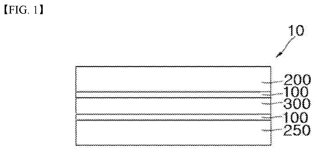
Image

Examples
example 2
PREPARATIVE EXAMPLE 2
Manufacture of Polarizer
[0064]A polyvinyl alcohol film (VF-PS6000, Kuraray Co., Ltd., thickness: 60 μm) washed with water at 25° C. was subjected to swelling in a swelling bath filled with water at 30° C. Then, the swollen film was dyed in a dyeing bath filled with an aqueous solution containing 1 ml / mol of potassium iodide at 30° C. for 65 seconds. The dyed film was allowed to pass through a wet crosslinking bath filled with an aqueous solution containing 3 wt % of boric acid at 30° C. Thereafter, the film was stretched to 6 times an initial length thereof in an aqueous solution containing 3 wt % of boric acid at 65° C. The stretched film was subjected to color complementation in a color complementation bath filled with an aqueous solution containing 4.5 wt % of potassium iodide and 2 wt % of zinc sulfate at 30° C. for 10 seconds or less. Then, the film was washed and dried, thereby providing a polarizer (thickness: 22 μm).
[0065](1) Polarizer: Polarizers of Pre...
example 1
[0075]A PET film was bonded to one surface of the polarizer prepared in Preparative Example 1 using the bonding agent 1 (first bonding layer, thickness: 2 μm). Then, a TAC film was bonded to the other surface of the polarizer prepared in Preparative Example 1 using the bonding agent 1 (second bonding layer, thickness: 2 μm). Then, an acrylic adhesive layer was formed on the other surface of the TAC film, thereby preparing a polarizing plate.
examples 2 to 6
[0076]Each of polarizing plates was prepared in the same manner as in Example 1 except that the kind of polarizer and the kind of protective layer were changed as listed in Table 2.
PUM
| Property | Measurement | Unit |
|---|---|---|
| RH | aaaaa | aaaaa |
| pH | aaaaa | aaaaa |
| storage modulus | aaaaa | aaaaa |
Abstract
Description
Claims
Application Information