Two-terminal current controller and related LED lighting device
a technology of led lighting devices and current controllers, applied in the direction of electric variable regulation, process and machine control, instruments, etc., can solve the problems of extra power, power factor of led lighting devices, and lower system efficiency
- Summary
- Abstract
- Description
- Claims
- Application Information
AI Technical Summary
Problems solved by technology
Method used
Image

Examples
first embodiment
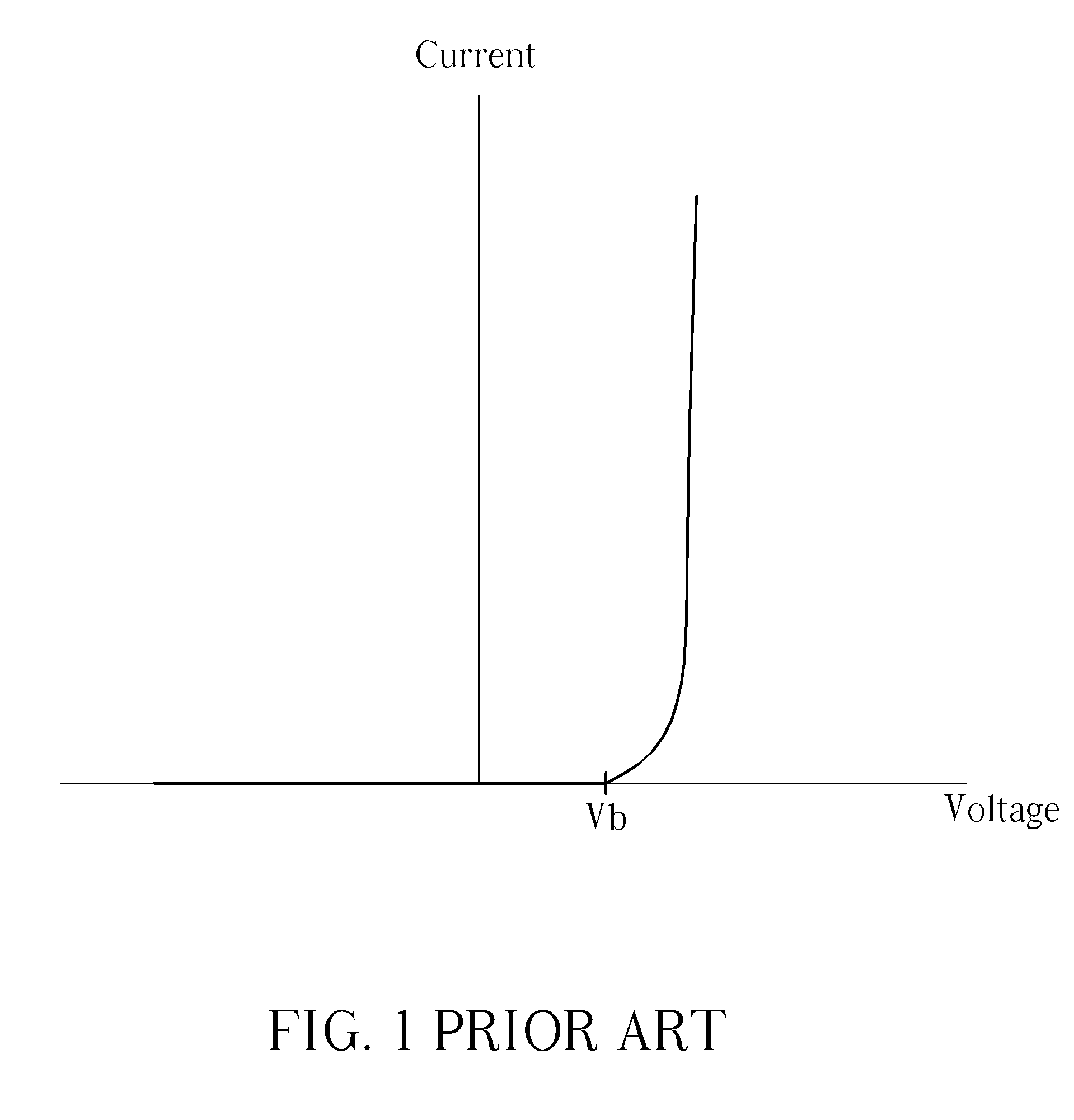
[0019]FIGS. 5 and 6 illustrate the operation of the LED lighting device 100, wherein FIG. 5 is a diagram illustrating the current-voltage chart of the two-terminal current controller 120, and FIG. 6 is a diagram illustrating the variations in the related current and voltage when operating the LED lighting device 100. In FIG. 5, the vertical axis represents the current IAK passing through the two-terminal current controller 120, and the horizontal axis represents the voltage VAK established across the two-terminal current controller 120. In the present invention, the two-terminal current controller 120 operates in a first mode and functions as a voltage-controlled device when 0AKDROP. In other words, when the voltage VAK exceeds the barrier voltage Vb′ of the two-terminal current controller 120, the current IAK changes with the voltage VAK in a specific manner; the two-terminal current controller 120 operates in a second mode and functions as a constant current source when VDROPAKOFF...
second embodiment
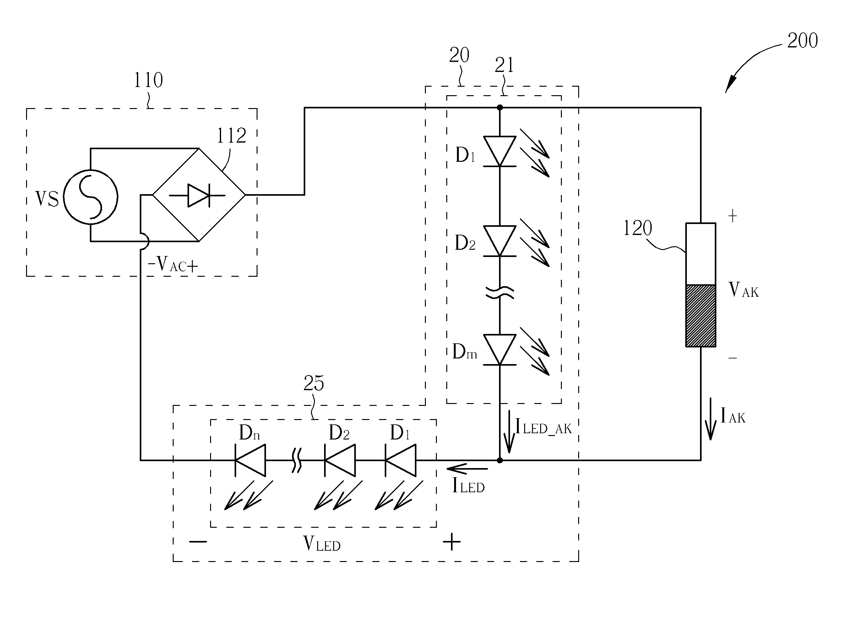
[0022]The two-terminal current controller 120 is configured to control the current passing through the luminescent device 20 according to the rectified AC voltage VAC, wherein IAK represents the current passing through the two-terminal current controller 120 and VAK represents the voltage established across the two-terminal current controller 120. In the present invention, the barrier voltage Vb′ of the two-terminal current controller 120 is smaller than the overall barrier voltage m*Vb of the luminescent element 21 (assuming the barrier voltage of each luminescent element is equal to Vb).
[0023]FIG. 8 is a diagram of an illustrated embodiment of the two-terminal current controller 120 in the LED lighting device 200. In this embodiment, the two-terminal current controller 120 includes a switch QN1, a control circuit 50, a current-detecting circuit 60, and a voltage-detecting circuit 70. The switch QN1 may include a field effect transistor (FET), a bipolar junction transistor (BJT) or...
third embodiment
[0052]Reference may also be made to FIG. 9 for the current-voltage chart of each two-terminal current controller in the LED lighting device 300. The values of VDROP1-VDROP4, VOFF—TH1-VOFF—TH4, VON—TH1-VON—TH4, VOFF—TH1′-VOFF—TH4′ and VON—TH1′-VON—TH4′ may be determined according to the maximum power dissipation and the maximum output current of the two-terminal current controllers 121-124, as well as the characteristics and the amount of the light-emitting diodes in use. FIG. 12 is a diagram illustrating the operation of the LED lighting device 300 according to the present invention. Since the rectified AC voltage VAC varies periodically with time, a cycle between t0-t10 is used for illustration, wherein the period between t0-t5 is the rising period of the rectified AC voltage VAC and the period between t5-t10 is the falling period of the rectified AC voltage VAC.
[0053]The operation of the LED lighting device 300 during the rising period t0-t5 is hereby explained. Between t0-t1 when...
PUM
 Abstract
Description
Claims
Application Information
 - R&D
- Intellectual Property
- Life Sciences
- Materials
- Tech Scout
- Unparalleled Data Quality
- Higher Quality Content
- 60% Fewer Hallucinations
Browse by: Latest US Patents, China's latest patents, Technical Efficacy Thesaurus, Application Domain, Technology Topic, Popular Technical Reports.
© 2025 PatSnap. All rights reserved.Legal|Privacy policy|Modern Slavery Act Transparency Statement|Sitemap|About US| Contact US: help@patsnap.com