Pump device

a technology of pumping device and pumping valve, which is applied in the direction of liquid fuel engines, machines/engines, rotary piston liquid engines, etc., can solve the problems of poor changeover response and inability to slide quickly, and achieve the effect of reducing the discharge volume and raising the oil pressur

Inactive Publication Date: 2015-01-06
YAMADA MANUFACTURING CO LTD
View PDF6 Cites 3 Cited by
  • Summary
  • Abstract
  • Description
  • Claims
  • Application Information

AI Technical Summary

Benefits of technology

[0012]Upon reduction of pressure in the chamber 66, moreover, the force of oil pressure that resists the reset spring 67 is insufficient. As a result, the displacement unit 60 cannot slide promptly, and changeover response is poor. Therefore, an object (technical problem to be solved) of the present invention is to provide a pump device in which oil pressure and discharge volume are gradually increased in accordance with values required by an engine or hydraulic equipment, so that the load exerted on the pump, the engine and so forth are can be kept to a minimum.
[0019]In the second invention, the driven gear unit is provided with the valve piston that comprises the small-diameter section having the main pressure-receiving surface, and the large-diameter section having the auxiliary pressure-receiving surface. Thereby, the pressure-receiving surface for the pressure of oil that flows from the main flow channel and the first branching flow channel is divided into two surfaces. The first flow channel control section performs switching between communication and shut-off of the first branching flow channel. At the time where the first branching flow channel is communicating, oil pressure acting on the auxiliary pressure-receiving surface from the first branching flow channel is added to the oil pressure acting on the main pressure-receiving surface from the main flow channel; as a result, the driven gear unit can move quickly in a direction of reducing the discharge volume, and the above-described operation can be controlled promptly, so that changeover response can be improved.
[0021]In the third invention, the first flow channel control section is provided with the solenoid valve and performs flow channel control of communication or shut-off of the first branching flow channel by way of the solenoid valve, and the second flow channel control section is provided with the spool valve, and performs flow rate control of communication or shut-off of the second branching flow channel by way of the spool valve. By virtue of this configuration, communication and shut-off between the large-diameter passage section of the driven gear unit chamber and the first branching flow channel is performed instantly, so that the discharge volume can be reduced quickly in accordance with the operation condition of the engine and hydraulic equipment.
[0023]In the fourth invention, the driven gear of the driven gear unit is formed to have an axial-direction total length dimension that is greater than that of a drive gear of the drive gear unit. As a result, the corners of the driven gear jut beyond those of the drive gear, and hence the driven gear can slide smoothly, without the corners of the latter biting onto the drive gear, as the driven gear starts sliding.
[0024]In the fifth invention, the timing of the first stage changeover is controlled through switching control of the spool valve based on oil pressure. As a result, changeover can be performed at an appropriate oil pressure, independently from oil temperature. The timing of the second stage changeover is controlled through switching control of the solenoid valve based on engine revolutions. As a result, changeover can be performed at the required timing, in accordance with the operating conditions of the engine. In the sixth invention, the timing of the second stage changeover is controlled through switching control of the solenoid valve based on engine revolutions and through switching control of the spool valve based on oil pressure. As a result, oil pressure can be raised reliably up to the required oil pressure.

Problems solved by technology

As a result, the displacement unit 60 cannot slide promptly, and changeover response is poor.

Method used


Image

  • Pump device
  • Pump device
  • Pump device

Examples


Embodiment Construction

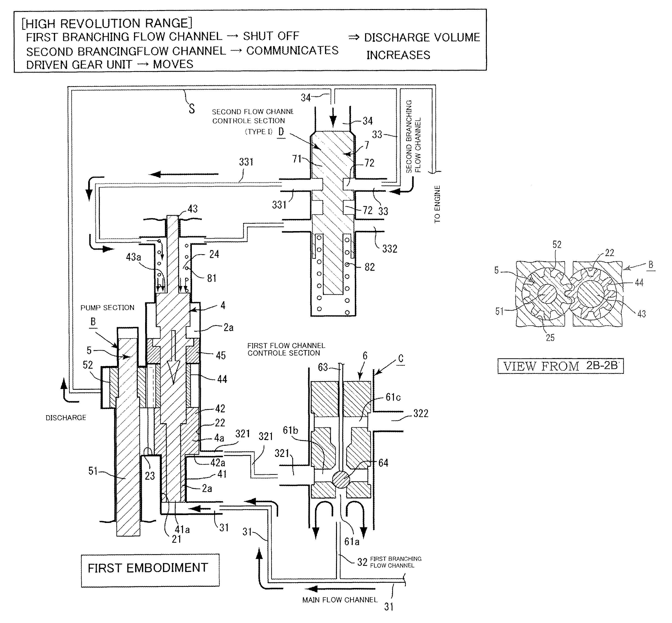
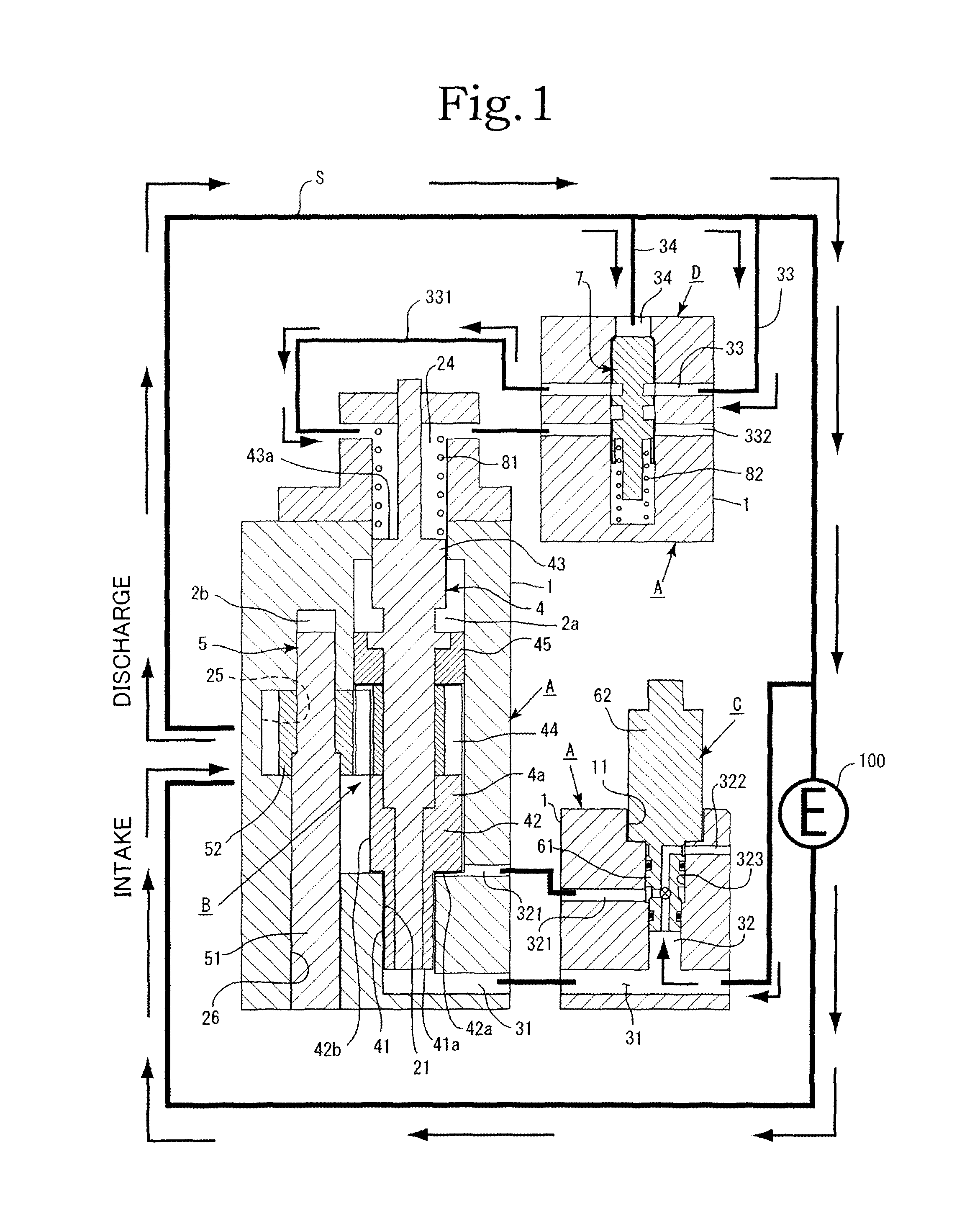
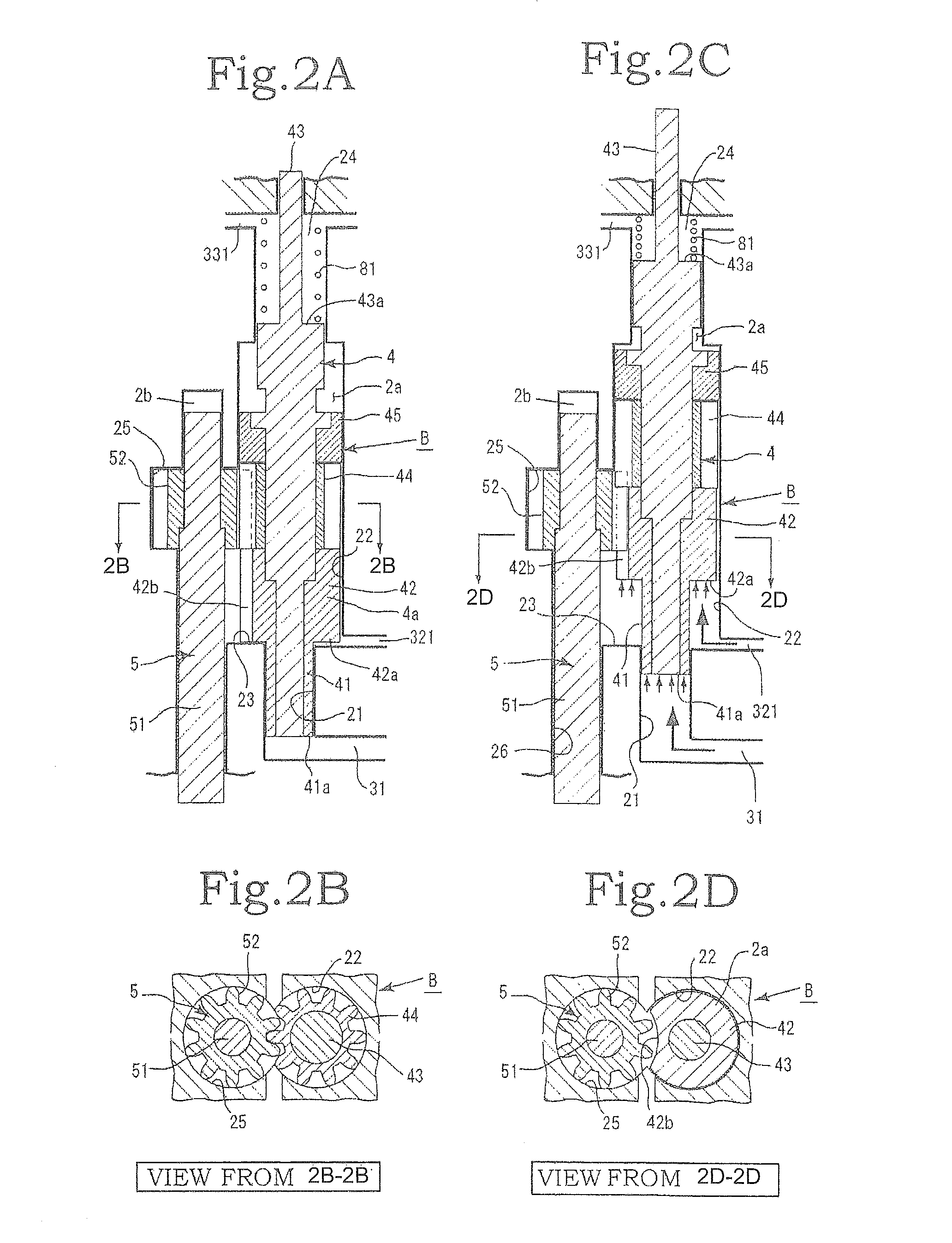
[0040]Embodiments of the present invention are described below with reference to accompanying drawings. The present invention has a first embodiment and a second embodiment depending on the configuration and operation. The configuration in the present invention includes mainly a housing A, a gear pump section B, a first flow channel control section C and a second flow channel control section D, as illustrated in FIG. 1 to FIG. 3. The gear pump section B comprises a driven gear unit 4 and a drive gear unit 5.

[0041]The first flow channel control section C comprises a solenoid valve 6. The second flow channel control section D comprises a spool valve 7. The second flow channel control section D may be of type I and type II in the first embodiment and the second embodiment, respectively. The second flow channel control section D in the first embodiment is of type I. The second flow channel control section D in the second embodiment is of type II. The second flow channel control section ...


PUM


Abstract

The invention has: a housing; a pump section formed of a drive gear unit and a driven gear unit; a main flow channel through which oil pressure is applied to the driven gear unit in a discharge volume reduction direction; a first branching flow channel through which oil pressure that assists oil pressure from the main flow channel is applied; a second branching flow channel through which oil pressure is applied to the driven gear unit in a discharge increase direction; a first flow channel control section; a second flow channel control section; and a spring that elastically urges the driven gear unit in a discharge increase direction. The first flow channel control section and the second flow channel control section can perform switching control in accordance with each increase or decrease of engine revolutions and in pressure.

Description

BACKGROUND OF THE INVENTION[0001]1. Field of the Invention[0002]The present invention relates to a pump device, in which in a variable capacity pump the pressure and discharge volume of oil are increased gradually in accordance with a value required by an engine or hydraulic equipment, and the load acting on the pump, the engine and so forth can be kept to a minimum.[0003]2. Description of the Related Art[0004]The theoretical discharge volume of a gear pump is determined ordinarily by, among other factors, tooth length and tooth width, and the discharge volume is determined by the theoretical discharge volume and the rotational speed of the gears (pump revolutions). In a case where such a gear pump is used, for instance, as an oil pump for supplying lubricating oil into an engine for vehicles, the theoretical discharge volume of the oil pump is set in such a manner that the necessary amount of oil can be supplied also when the output of the engine, as a driving source, is low and pu...

Claims


Application Information

Patent Timeline
Patent Type & Authority Patents(United States)
IPC IPC(8): F04C14/18F04C2/14
CPCF04C2/14F04C14/185
Inventor WATANABE, MANABUMIYAJIMA, JUNICHIIZUTSU, MASATOWATANABE, TAKATOSHI
Owner YAMADA MANUFACTURING CO LTD
Why Eureka
Try Eureka