Liquid crystal display devices and methods for driving the same
a liquid crystal display and display device technology, applied in the direction of instruments, computing, electric digital data processing, etc., can solve the problems of insufficient liquid crystal response speed, inability to achieve a target luminance, etc., to suppress the blur of moving images, and improve the response speed of liquid crystal.
- Summary
- Abstract
- Description
- Claims
- Application Information
AI Technical Summary
Benefits of technology
Problems solved by technology
Method used
Image
Examples
embodiment 1
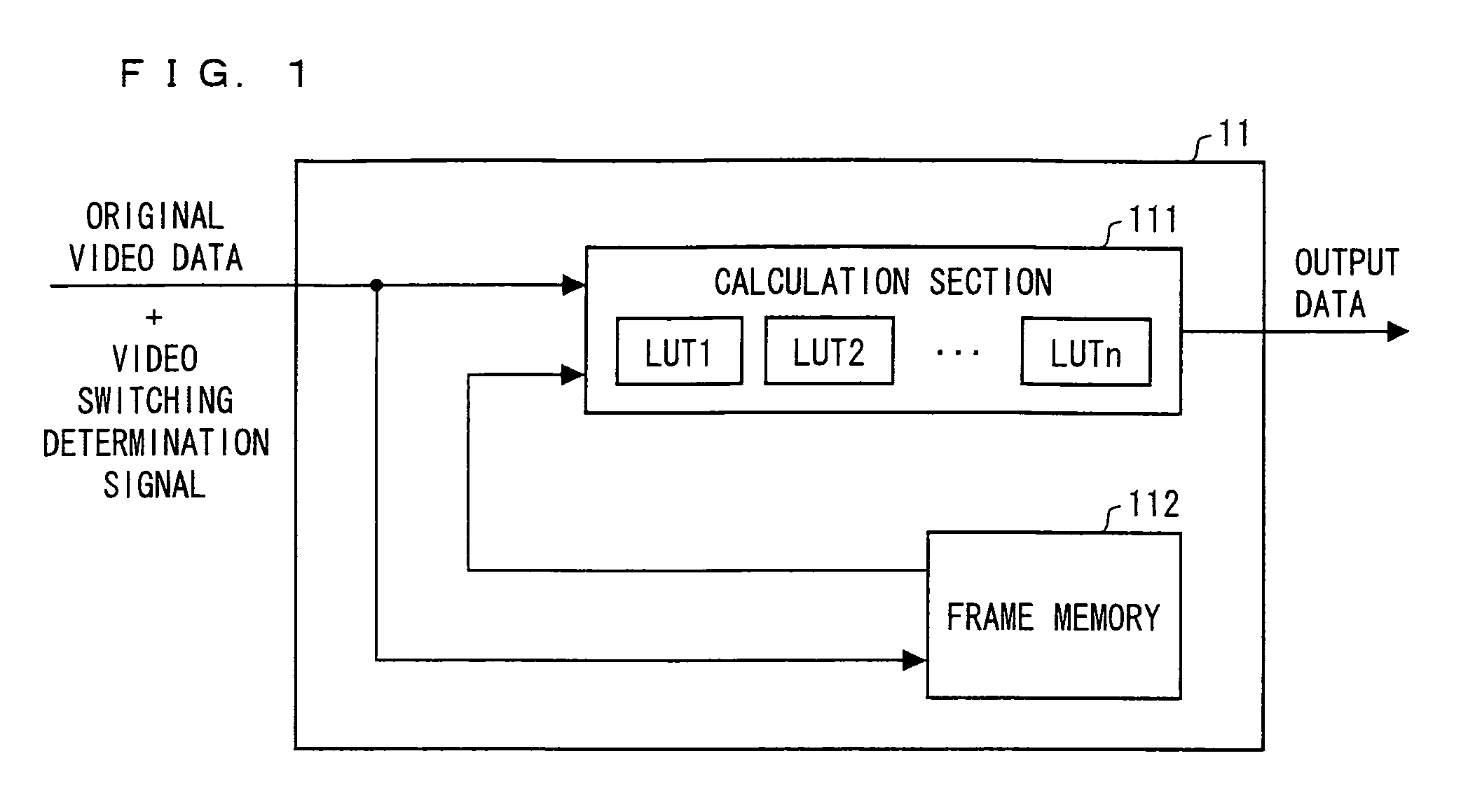
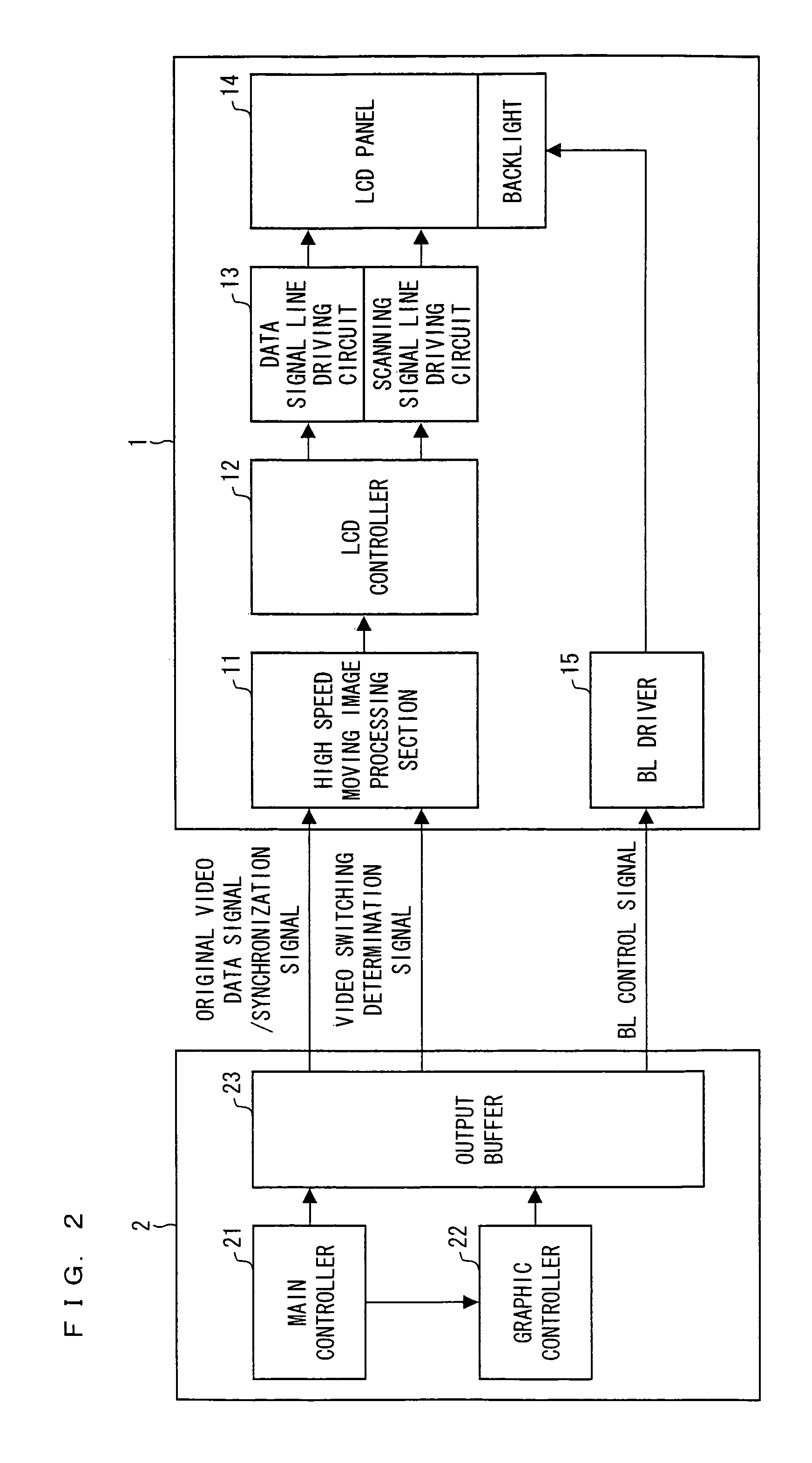
[0036]One embodiment of the present invention is described below with reference to FIG. 1 through FIG. 9. First, with reference to FIG. 2, a schematic configuration of a liquid crystal display device according to Embodiment 1 is described.
[0037]A liquid crystal display device 1 of FIG. 2 includes a high speed moving image processing section 11, an LCD (Liquid Crystal Display) controller 12, an LCD driver 13, an LCD panel 14, and a BL (Back Light) driver 15. Further, the liquid crystal display device 1 receives a video data signal and a display control signal, supplied from a host device 2, so as to display an image. Here, in case of applying the present invention to a mobile phone, a personal computer, or the like for example, the liquid crystal display device 1 is a liquid crystal display module, and the host device 2 is a CPU of the mobile phone, the personal computer, or the like.
[0038]The host device 2 outputs video data, generated by a graphic controller 22, via an output buffe...
embodiment 2
[0055]In Embodiment 1, the n number of writing operations are carried out with respect to the LCD panel 14 during a single frame period, and the host device 2 transmits data to the liquid crystal display device 1 n times in a single frame in response to the n number of writing operations. In this case, it is necessary to transmit data from the host device 2 to the liquid crystal display device with high speed. This results in a higher power consumption for the data transmission.
[0056]Embodiment 2 describes a case where video data is transmitted from the host device 2 to the liquid crystal display device 1 once in a single frame. Note that, a schematic configuration of the liquid crystal display device according to Embodiment 2 is the same as that illustrated in FIG. 2.
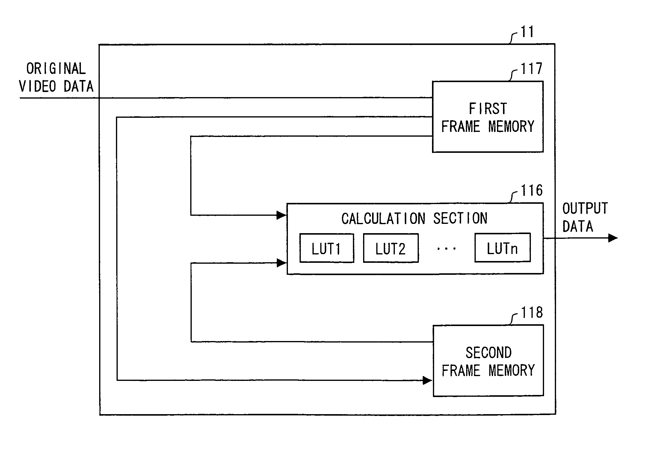
[0057]With reference to FIG. 4, a configuration and operation of a high speed moving image processing section 11 according to Embodiment 2 are detailed as follows.
[0058]The high speed moving image processing section 11...
embodiment 3
[0070]In Embodiment 2, data is transmitted from the host device 2 to the liquid crystal display device 1 only once in a single frame thereby carrying out the writing with respect to the LCD panel 14 n times in a single frame period. However, in Embodiment 2, two frame memories are required in the high speed moving image processing section 11. The number of memories increases, which results in higher cost.
[0071]Embodiment 3 describes a case where video data is transmitted from the host device 2 to the liquid crystal display device 1 only once in a single frame and a single frame memory is used. Note that, a schematic configuration of the liquid crystal display device according to Embodiment 3 is the same as that illustrated in FIG. 2.
[0072]With reference to FIG. 8, a configuration and operation of a high speed moving image processing section 11 according to Embodiment 3 are described as follows.
[0073]The high speed moving image processing section 11 of FIG. 8 includes a calculation s...
PUM
 Abstract
Description
Claims
Application Information
 - R&D
- Intellectual Property
- Life Sciences
- Materials
- Tech Scout
- Unparalleled Data Quality
- Higher Quality Content
- 60% Fewer Hallucinations
Browse by: Latest US Patents, China's latest patents, Technical Efficacy Thesaurus, Application Domain, Technology Topic, Popular Technical Reports.
© 2025 PatSnap. All rights reserved.Legal|Privacy policy|Modern Slavery Act Transparency Statement|Sitemap|About US| Contact US: help@patsnap.com


