Driving system and method for an electroluminescent display

a technology of driving system and electroluminescent display, applied in the direction of instruments, static indicating devices, etc., can solve the problem of requiring greater power consumption, and achieve the effect of less power demand, faster response, and reduced power demand for lighting up the electroluminescent elements

Inactive Publication Date: 2010-10-05
RICHTEK TECH
View PDF8 Cites 56 Cited by
  • Summary
  • Abstract
  • Description
  • Claims
  • Application Information

AI Technical Summary

Benefits of technology

[0006]An object of the present invention is to provide a driving system and method for an electroluminescent display to attain less power demand and faster response.
[0007]In an electroluminescent display having a driving system to drive an array of electroluminescent elements according to a display data, the anodes of the electroluminescent elements on the same column are electrically connected to one of a plurality of anode lines, and the cathodes of the electroluminescent elements on the same row are electrically connected to one of a plurality of cathode lines. In the driving system, according to the present invention, a row and column control circuit generates two control signals from the display data, an anode line driving circuit in response to the first control signal switches each of the anode lines among connections of a current source, a first node and ground, and a cathode line scanning circuit in response to the second control signal switches each of the cathode lines among connections of a reverse voltage, a second node and ground, wherein the first and second nodes are electrically connected together. When one or more of the electroluminescent elements are to be lighted up, the anode lines connected to their anodes and the anode lines connected to the electroluminescent elements currently being canned are switched to connect to the respective first nodes, and the cathode lines connected to their cathodes and the cathode lines connected to the electroluminescent elements currently being canned are switched to connect to the respective second nodes, such that part of the electric charges in the electroluminescent elements currently being lighted up are recycled and transferred to the electroluminescent elements to be lighted up. Therefore, the power demand to light up the electroluminescent elements is reduced. Further, before the anode line is switched from the first node to the current source, it is switched to connect to a power source to precharge thereto, so as to enhance the response speed of lighting up the electroluminescent elements to be lighted up.

Problems solved by technology

In this driving scheme, however, all the anodes and cathodes of the electroluminescent elements are grounded for the electric charges thereon to be completely discharged before an electroluminescent element is lighted up and as a result, each time the electroluminescent element is charged from 0 V when it is to be lighted up, which requires greater power consumption.

Method used


Image

  • Driving system and method for an electroluminescent display
  • Driving system and method for an electroluminescent display
  • Driving system and method for an electroluminescent display

Examples


Embodiment Construction

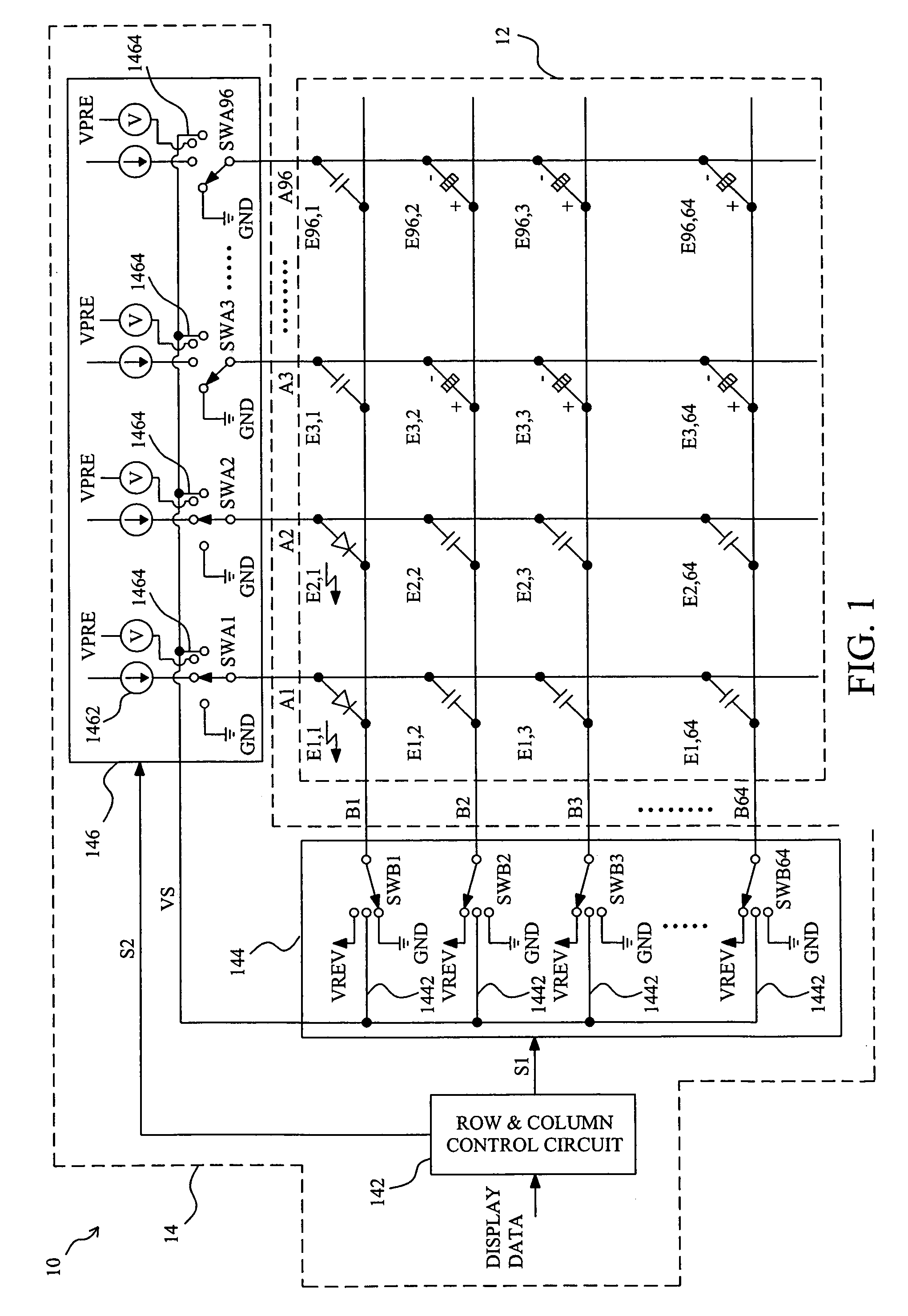
[0013]FIG. 1 schematically depicts an electroluminescent display 10, which comprises an array 12 of organic electroluminescent elements Ex,y (x=1, 2, . . . , 96; y=1, 2, . . . , 64) and a driving system 14 connected to the organic electroluminescent elements Ex,y with a plurality of drive lines Ax (x=1, 2, . . . , 96) and a plurality of scan lines By (y=1, 2, . . . , 64). In the array 12, the organic electroluminescent elements Ex,y are arranged in such a manner that the anodes of the organic electroluminescent elements Ei,y on the i-th column are connected to the i-th anode line Ai, and the cathodes of the organic electroluminescent elements Ex,j on the j-th row are connected to the j-th cathode line Bj. In the driving system 14, a row and column control circuit 142 generates two control signals S1 and S2 according to a display data for a cathode line scanning circuit 144 and an anode line driving circuit 146, respectively, such that each of the cathode lines B1-B64 is switched amo...


PUM


Abstract

A driving system and method for electroluminescent displays which by connecting the electroluminescent elements that have been lighted up to the electroluminescent elements that are to be lighted up causes charge to be shared among the elements, so as to increase the voltage level at the anodes of the electroluminescent elements which are to be lighted up, thereby reducing the power consumption and increasing the response speed.

Description

FIELD OF THE INVENTION[0001]The present invention is related generally to an electroluminescent display and, more particularly, to a driving system and method for an electroluminescent display.BACKGROUND OF THE INVENTION[0002]A typical electroluminescent display comprises an array of electroluminescent elements arranged in rows and columns in which the anodes of the electroluminescent elements on each row are electrically connected to one of a plurality of anode lines and the cathodes of the electroluminescent elements on each column are electrically connected to one of a plurality of cathode lines, and a driving system to switch the anode lines and the cathode lines between two phases according to display data for specifically lighting up one or ones of the electroluminescent elements.[0003]To speed up the electroluminescent elements in an electroluminescent display to light up, the driving system disclosed by U.S. Pat. No. 5,844,368 to Okuda et al. precharges the electroluminescen...

Claims


Application Information

Patent Timeline
Patent Type & Authority Patents(United States)
IPC IPC(8): G09G3/10
CPCG09G3/3216G09G2310/0251G09G2310/0256
Inventor CHEN, CHIEN-CHUNGLIN, HSAN-FONGYANG, SHEI-CHIE
Owner RICHTEK TECH
Why Eureka
Try Eureka