Switchboard apparatus and method

a technology of switchboard and switch body, which is applied in the field of switchboards, can solve the problems of no useful work, high cost and difficulty in implementation, and the use of power factor correction on the customer side is newer and more difficult, so as to reduce power consumption, less power loss, and cost saving for the customer

Inactive Publication Date: 2009-05-07
GENERAL ELECTRIC CO
View PDF6 Cites 9 Cited by
  • Summary
  • Abstract
  • Description
  • Claims
  • Application Information

AI Technical Summary

Benefits of technology

[0009]A switchboard apparatus is provided for power factor correction. Lower and upper limits are provided for desired power factor. The exemplary embodiment of the invention determines power factor, compares power factor to the limits and corrects power factor by connecting or disconnecting capacitor load. The capacitor load changes or corrects the power factor. By correcting power factor on a customer side of an electric system, a customer would get less power loss and have less power demand from the power supplier (i.e. electric utility). This could result in cost savings to the customer.

Problems solved by technology

Reactive power, which is needed to generate magnetic fields required for operation of inductive electrical equipment, but performs no useful work.
The use of power factor correction on the customer side is newer and has been expensive and difficult to implement due to cost of equipment, size factors and the lack of commercially available packages for installation at a customer site, with ease.

Method used


Image

  • Switchboard apparatus and method
  • Switchboard apparatus and method
  • Switchboard apparatus and method

Examples


Embodiment Construction

Power Factor Introduction

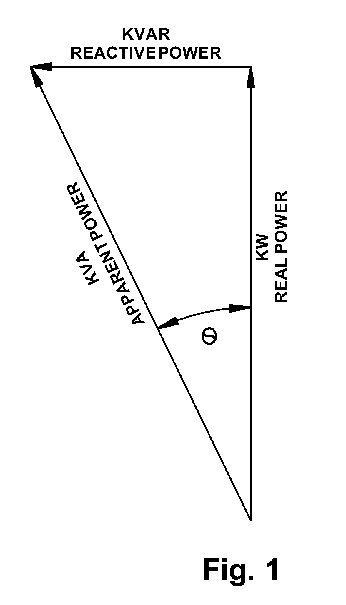
[0021]Power factor (PF) is the relationship between the phase angle of voltage and resultant current through the loads. Hence, power factor can be calculated as a ratio. Power factor may be referenced herein as power factor, PF, power factor ratio, or PF ratio. The PF ratio is calculated as the cosine of the phase angle between voltage and current, which is the same as the ratio between KW (real power) and KVA (apparent power); see equation (3) below.

=lag between voltage and current  (1)

PowerFactororPF=cosϑ=realpowerapparentpower=1kW1kVA(2)

[0022]Where real power is power that can be used on the load side of a switchboard and apparent power is generated power needed from a supplier, such as an electric utility company.

[0023]Solving equation (2) for power factor:

real power=cos *apparent power  (3)

[0024]Solving equation (3) for apparent power:

realpowercosϑ=apparentpower(4)

[0025]And substituting power factor for cosine theta:

realpowerPF=apparentpower(5)

[0026]Ide...


PUM


Abstract

A switchboard apparatus and method are provided including a switchboard bus with conductors secured to the switchboard apparatus; a power quality meter operatively connected to the switchboard bus to obtain bus voltage and current. The apparatus also includes a capacitor operatively connected to and electrically in-parallel with the switchboard bus; the at least one capacitor further including a switch, the switch configured to open and close so as to connect and disconnect the capacitor operatively connected to the switchboard bus upon the occurrence of predetermined conditions; a controller controls the switch. The capacitor is connected to and disconnected from the switchboard bus as a function of the power factor.

Description

BACKGROUND OF THE INVENTION[0001]1. Field of the Invention[0002]The present disclosure is related to switchboards. More particularly, the present disclosure is related to switchboards and the efficiency of electric power loads connected thereto.[0003]2. Description of Related Art[0004]Power factor (PF) is the ratio of useful current to total current. It is also the ratio of useful power expressed in kilowatts (KW) to total power expressed in kilovolt-amperes (KVA). Another expression of power factor is the relationship between the phase angle of voltage and resultant current through the loads. The power factor may be calculated as ratio of the cosine of the phase angle between voltage and current which is the same as the ratio between KW (real power) and KVA (apparent power).[0005]Power factor is usually expressed as a decimal or as a percentage. Ideally, the current through the loads is exactly in phase with the generated voltage, having neither a leading phase angle nor lagging ph...

Claims


Application Information

Patent Timeline
Patent Type & Authority Applications(United States)
IPC IPC(8): H02B1/20H02H3/42
CPCY02E40/30H02J3/1828
Inventor LETOURNEAU, WILLIAM ROBERTSTILLWELL, RICHARD
Owner GENERAL ELECTRIC CO
Why Eureka
Try Eureka