Energy storage system for elevators

a technology for energy storage and elevators, applied in the field of elevator systems, can solve the problems of inability to operate in all operating situations, inability to discharge energy storage, and high power consumption of filter components in the mains inverter of elevator systems, so as to reduce the average power of the elevator system, reduce the total power, and discharge energy storage.

Inactive Publication Date: 2010-03-23
KONE CORP
View PDF16 Cites 36 Cited by
  • Summary
  • Abstract
  • Description
  • Claims
  • Application Information

AI Technical Summary

Benefits of technology

[0015]The elevator system and energy storage arrangement of the invention have the advantage of allowing economical use of non-counterweighted elevators as the connection power required by the elevator system and the main fuse size of the elevator system are smaller than in prior-art systems. Another advantage achievable by the invention is that electricity network harmonics can be more easily and economically suppressed in non-counterweighted elevator systems as the connection power is reduced and lower-power filters can be used. Furthermore, the invention can provide a saving in costs of the power converter unit between the electricity network and the elevator system as this unit can be designed for a lower power rating than conventionally.
[0016]Another advantage achievable by the invention is that energy can be stored for a long time, e.g. for the time between morning and afternoon peak traffic hours, but even for periods longer than this. Further, the energy storages in the elevator system of the invention are nature-friendly and durable, and they can be recharged an unlimited number of times.

Problems solved by technology

This is not possible in all operating situations in the elevator system, in which case the power generated may have to be dissipated in resistors or in some other similar way.
Filters provided in the mains inverter of elevator systems are expensive when designed for high powers.
It may also happen that the internal electric network of the building can not receive the power produced by elevators without counterweight, in which case the voltage in the internal electric network of the building will rise.
When a building is to be provided with several elevators, as an elevator group or otherwise, the connection power required by the elevators easily increases to a level that makes it unreasonable to use elevators without counterweight in the building, although they offer a significant space saving.
However, as the power generated by an elevator without counterweight is considerably greater than that produced by a counterweighted elevator, the size of supercapacitors needed to store the energy produced would increase significantly in the case of an elevator without counterweight, so the energy storage would be expensive and take up a large space.
Furthermore, the service life of supercapacitors is limited, typically about 30 000 hours, and, due to leakage currents, they are particularly well suited only for short-term storage of energy.
Optimization of elevator running schedules and prior-art electric energy storage solutions can not be regarded as offering an optimal solution for minimization of the size of the electric network connection of non-counterweighted elevator systems.
If the use of an elevator's energy storage is limited to one elevator, implementing an energy storage in an elevator system comprising a plurality of elevators will be complicated in practice.

Method used


Image

  • Energy storage system for elevators
  • Energy storage system for elevators
  • Energy storage system for elevators

Examples


Embodiment Construction

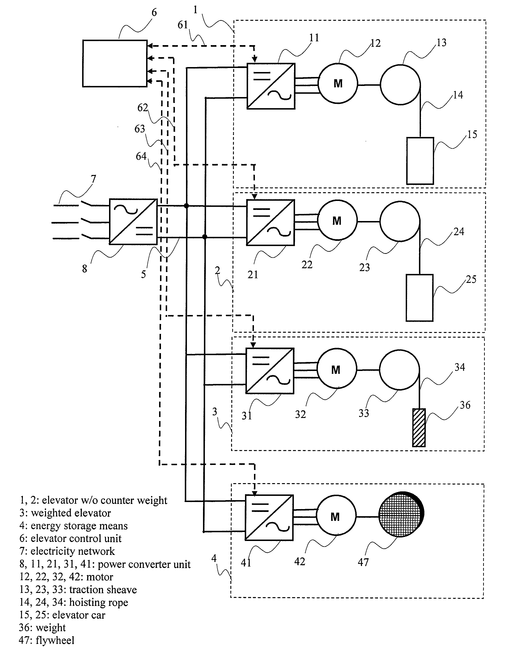
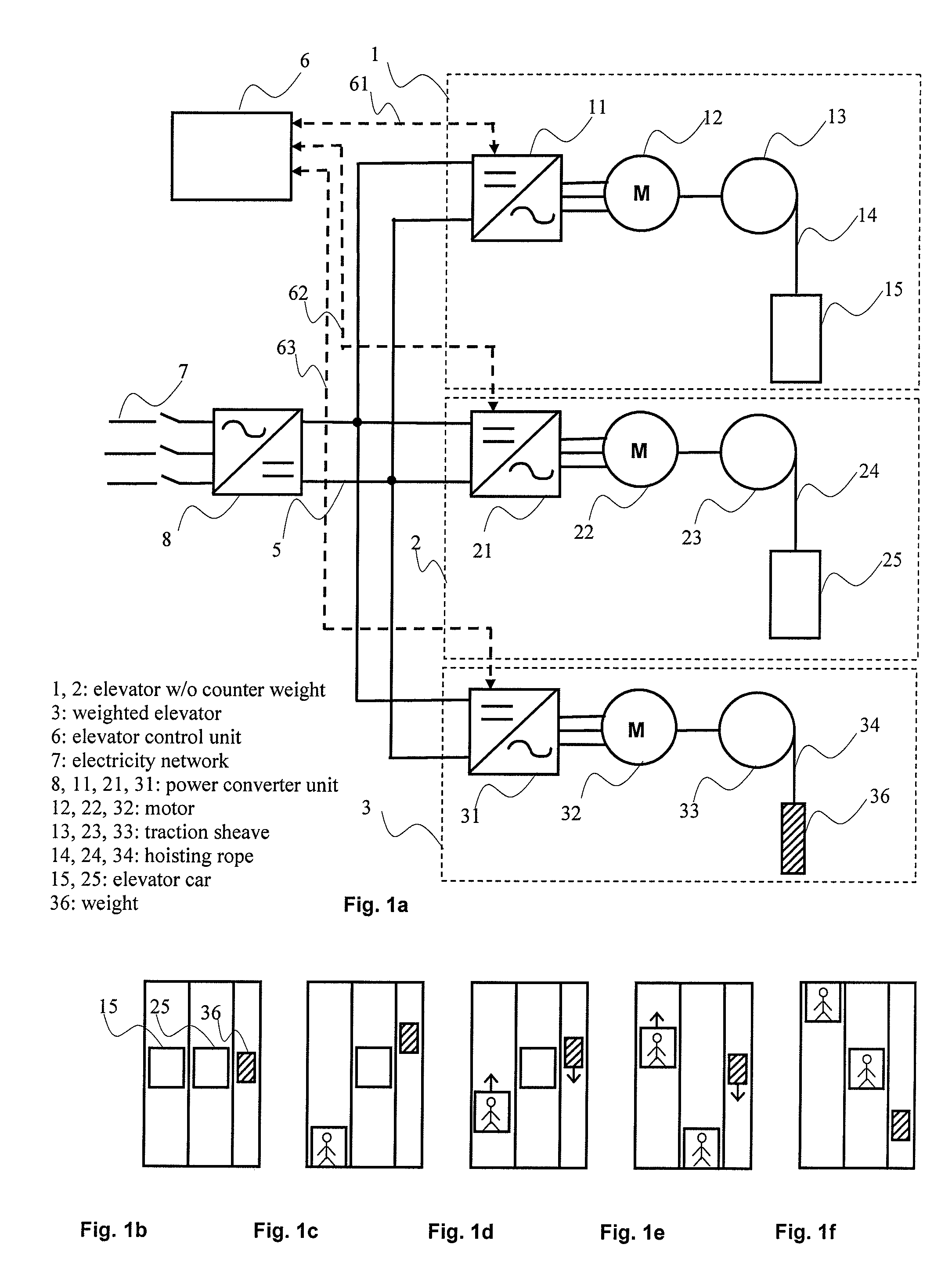
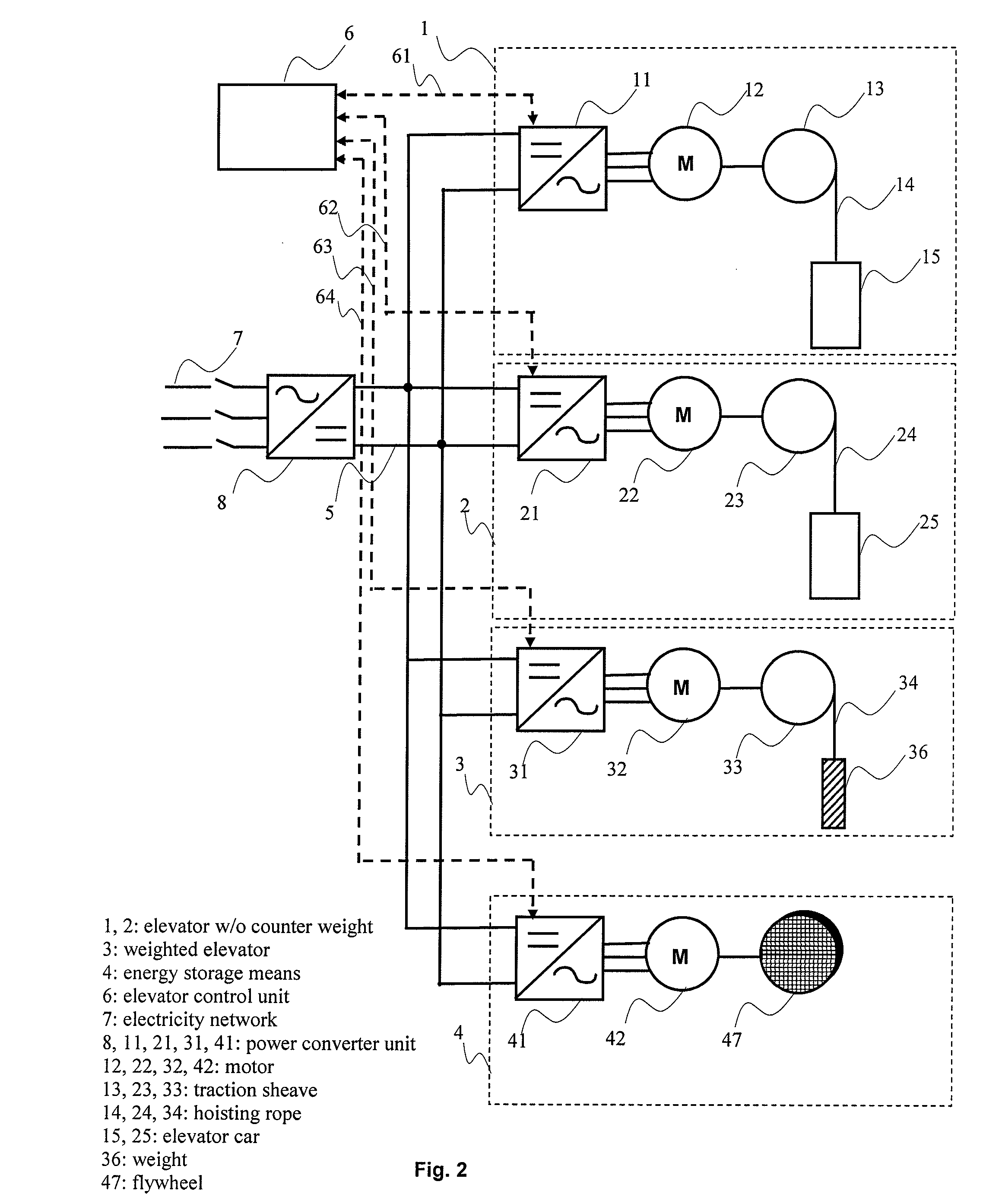
[0024]In non-counterweighted elevator systems, when the elevator car is moving downwards, potential energy of the elevator car is converted by the elevator motor into electric energy, and when the elevator car is moving upwards, its potential energy increases. As compared to counterweighted elevators, the instantaneous levels of power required and produced by non-counterweighted elevators are high. The power levels are proportional to the speed of the elevator. In the elevator system of the invention, one or more common energy storages are provided for an elevator or a number of elevators. The elevator system of the invention comprises at least one elevator without counterweight and means for storing mechanical energy and discharging an energy storage. When the elevator without counterweight is moving downwards, the change in potential energy of the elevator car can be at least partly converted into mechanical energy of the energy storage, and the energy stored in the energy storage...


PUM


Abstract

An elevator system and a method for reducing total power in an elevator system are provided. The elevator system includes at least one elevator without counterweight for moving people and / or goods. The elevator without counterweight comprises a power converter unit, an elevator motor, a traction sheave, a set of hoisting ropes and an elevator car. The elevator system also includes means for storing mechanical energy and discharging an energy storage.

Description

[0001]This application is a Continuation of co-pending Application No. PCT / F12006 / 000407filed on Dec. 8, 2006, and for which priority is claimed under 35 U.S.C. § 120; and this application claims priority of Application No. 20051343 filed Finland on Dec. 30, 2005 under 35 U.S.C. § 119; the entire contents of all are hereby incorporated by reference.FIELD OF THE INVENTION[0002]The present invention relates to an elevator system as defined in the preamble of claim 1 and to a method for reducing the total power in an elevator system as defined in the preamble of claim 9.BACKGROUND OF THE INVENTION[0003]The power required by the hoisting machine of an elevator varies depending on factors including load, speed, traveling direction and phase of the operating cycle of the elevator. It is advantageous to keep the power requirement as small as possible to minimize both the size of the hoisting machine and the required mains connection size. A traditional solution designed to minimize the pow...

Claims


Application Information

Patent Timeline
Patent Type & Authority Patents(United States)
IPC IPC(8): B66B1/06B66B1/30
CPCB66B1/302B66B1/30B66B1/308B66B1/06B66B11/0484
Inventor AULANKO, ESKOSYRMAN, TIMOKORVENRANTA, SAKARIJAHKONEN, PEKKA
Owner KONE CORP
Why Eureka
Try Eureka