Power tool

a power tool and power technology, applied in the field of power tools, can solve the problems of high manufacturing and assembly cost, and achieve the effects of simplifying the switching mechanism, simplifying the construction of the seesaw lever, and complex linkages

Inactive Publication Date: 2006-06-29
BLACK & DECKER INC
View PDF36 Cites 41 Cited by
  • Summary
  • Abstract
  • Description
  • Claims
  • Application Information

AI Technical Summary

Benefits of technology

[0012] The seesaw lever simplifies the switching mechanism because it is one single component that can control the position of the first and second drive sleeves simultaneously.
[0013] Preferably, the mode change mechanism further comprises a first biasing means adapted to bias the claw portions of the first drive sleeve and the first gear into engagement and a second biasing means adapted to bias the claw portions of the second drive sleeve and the second gear into engagement. Thus, the claw portions are normally in engagement and the engaging portions of the seesaw lever need only abut the drive sleeves in a direction opposing to the bias of these biasing means in order to control the position of the drive sleeves. This has the advantage of simplifying the construction of the seesaw lever and the drive sleeves because the need for complex linkages between the seesaw lever and drive sleeves is eliminated.
[0014] Preferably, the first and second drive sleeves have the shape of a hat with a flange protruding radially. This has the advantage that the engaging portions of the seesaw lever need only abut the underside of the flanges of the drive sleeves which is a simple construction. It has the further advantage that the engaging portions can be shaped to neatly surround the drive sleeves by abutting the majority of the underside of the flanges thereby providing more solid support for the drive sleeves.
[0015] Preferably the switching mechanism further comprises a control plate rotatably connected to the housing, a control finger connected to the control plate and protruding outwardly therefrom towards the seesaw lever wherein the control finger protrudes through at least one elongate slot in the seesaw lever, wherein the control finger is located eccentrically in relation to the rotational axis of the control plate and the elongate slot is located eccentrically in relation to the pivotal axis of the seesaw lever so that rotation of the control plate results in pivotal movement of the seesaw lever from one side to the other. This has the advantage that control plate has positive control of the seesaw lever because the control finger is always captive inside the elongate slot. This avoids the need for extra components like, for example, springs, to return the seesaw lever to one position or another. Further, the sliding movement of the control finger inside the elongate slot neatly converts rotational movement of the control plate into bi-directional pivotal movement of the seesaw level which, in turn, selectively moves the first or the second drive sleeve along their respective linear paths. This is achieved without any additional linkages which results in a simple and compact switching mechanism. It also means that the switching mechanism does not need any stops because the seesaw lever pivots from side to side whether the control plate is rotated clockwise or anti-clockwise. This has the advantage of further simplifying the switch mechanism and saving cost.

Problems solved by technology

Therefore, the switching mechanism is a relatively complex system involving several moving parts which make it expensive to manufacture and assemble.

Method used


Image

  • Power tool
  • Power tool
  • Power tool

Examples


Embodiment Construction

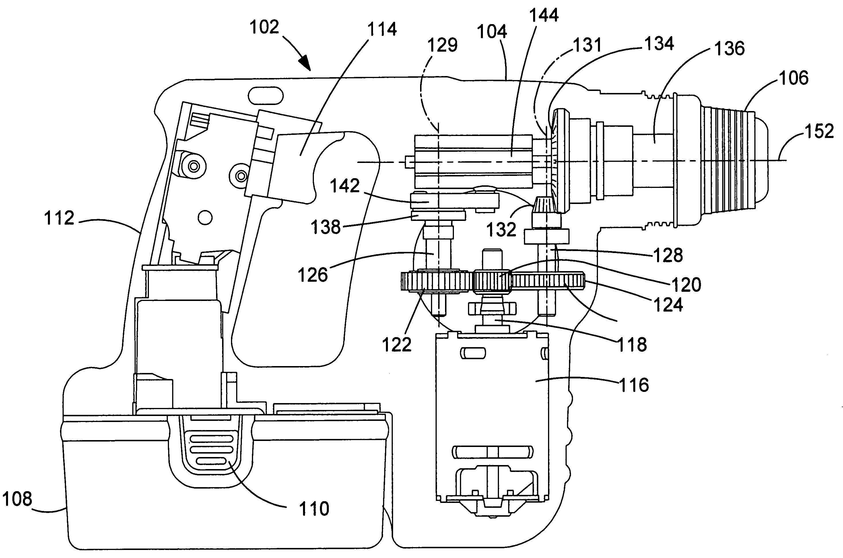
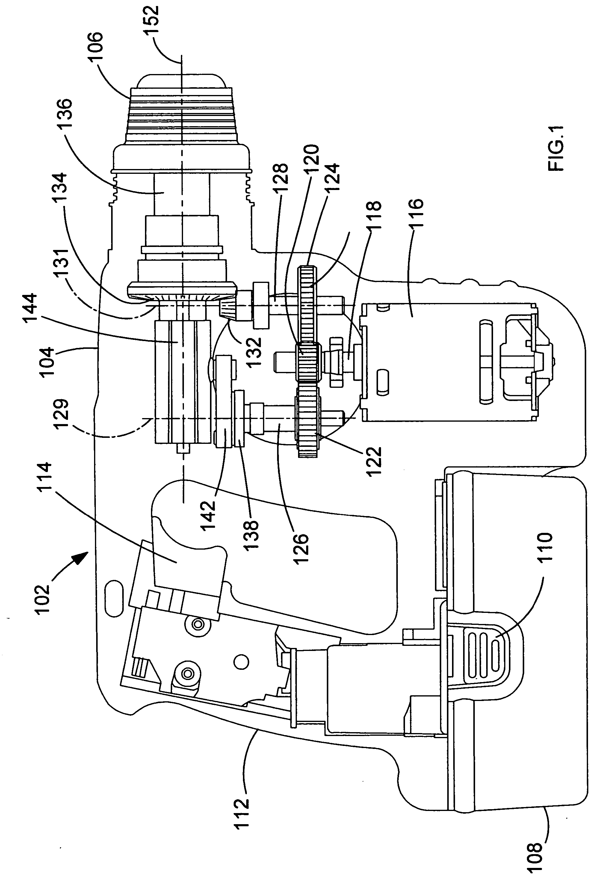
[0031] Referring to FIG. 1, a hammer drill shown generally by 102 comprises a housing 104 formed from at least two clamshell halves of durable plastics material, as will be understood by persons skilled in the art. Extending from a forward end of housing 104 is a chuck 106 or similar device for gripping a drill bit (not shown). A rechargeable battery pack 108 is detachably fixed to the bottom of the housing, and can be detached from the housing 104 by depressing clips 110 to release the battery pack for the purpose of recharging or exchange. The housing 104 comprises a handle portion 112 having a trigger switch 114. An electric motor 116 is disposed in the housing. The motor is electrically coupled to the battery pack via the trigger switch. The trigger switch is for selectively energising the motor to operate the hammer drill. An output shaft 118 extends from the motor 116. The output shaft 118 has a pinion 120 formed thereon. The pinion 120 meshes with a first gear 122 and a secon...


PUM

PropertyMeasurementUnit
reciprocating striking forceaaaaaaaaaa
rotational forceaaaaaaaaaa
movementaaaaaaaaaa

Abstract

A gear wheel is rotatably mounted on a drive shaft. The drive shaft has a plurality of longitudinal splines formed thereon. A drive sleeve surrounds the drive shaft and has a plurality of the inner splines formed on its interior surface. The inner splines slidably intermesh with outer splines of the drive shaft such that the drive sleeve can slide up and down on but cannot rotate relative to the drive shaft. A coil spring biases the drive sleeve downwardly. Drive sleeve teeth are formed around the bottom edge of the drive sleeve. Corresponding gear plate teeth are formed on the upper surface of the gear wheel and are adapted to engage the drive sleeve teeth when the drive sleeve is in its downward most position under the influence of the coil spring. In this position, the gear wheel is operatively coupled to the drive shaft.

Description

FIELD OF THE INVENTION [0001] The present invention relates to a power tool. The invention relates particularly, but not exclusively, to a mode change mechanism for selecting a hammering mode, a rotary mode, and a combined hammering and rotary mode, and to a power tool incorporating such a mode change mechanism. BACKGROUND OF THE INVENTION [0002] Hammers drills are power tools which can operate in one of three modes of operation. Generally, a hammer drill will have a tool bit which can be operated in a hammering mode, a rotary mode and a combined hammering and rotary mode. [0003] Hammer drills also generally comprise a mode change mechanism which enables a user to select between the different modes of operation of the hammer drill. [0004] European patent application EP0759342 discloses a hammer drill having a mode change mechanism comprising an axially slidable lock ring which is disposed on the spindle of the hammer drill. The rotational mode of the hammer drill is selected by rota...

Claims


Application Information

Patent Timeline
Patent Type & Authority Applications(United States)
IPC IPC(8): E02D7/02
CPCB25D16/006B25D2211/003B25D2216/0015B25D2216/0023B25D2216/0038
Inventor SOIKA, MARTINHANKE, ANDREASNEMETZ, UWEKUNZ, MICHAEL
Owner BLACK & DECKER INC
Why Eureka
Try Eureka