Safety syringe with disposable components after use

a safety syringe and disposable technology, applied in the field of safety syringes, can solve the problems of increasing the operation cost of a hospital, contaminating the medical worker with microorganisms, and stainless steel syringes, so as to eliminate the possibility of contamination and save costs

Inactive Publication Date: 2008-04-24
LIAO SHOU CAI +1
View PDF12 Cites 35 Cited by
  • Summary
  • Abstract
  • Description
  • Claims
  • Application Information

AI Technical Summary

Benefits of technology

[0006]It is therefore an object of the present invention to provide a safety syringe which, after use, some components thereof are discarded for eliminating the possibility of contamination, and the remaining components can be sterilized for future use for the purposes of saving cost and environmental protection.

Problems solved by technology

Conventionally, a syringe for dispensing anesthetic is made of stainless steel and which is relatively high in cost.
However, it is highly possible that the needle may accidentally prick fingers of a medical worker and thereby contaminate the medical worker with microorganisms.
Inevitably, however, such disposing may greatly increase operation cost of a hospital.
This is also not desirable.

Method used


Image

  • Safety syringe with disposable components after use
  • Safety syringe with disposable components after use
  • Safety syringe with disposable components after use

Examples


first embodiment

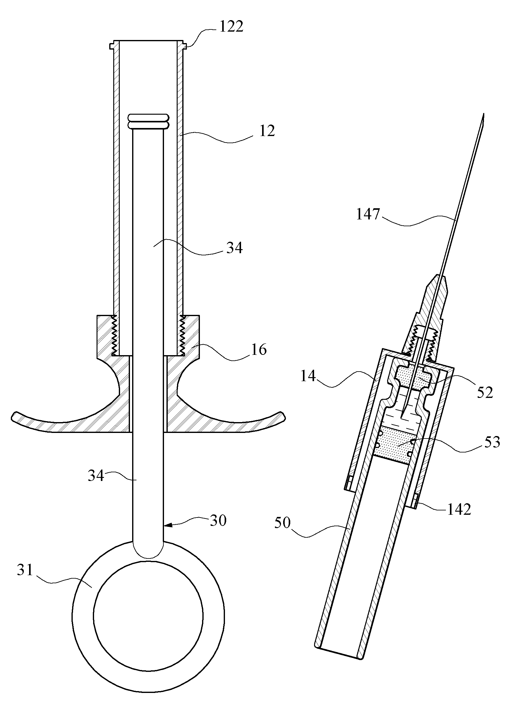
[0036]Referring to FIGS. 4, 5, and 6, further assembly and a fluid dispensing operation of the first configuration of the first embodiment will be described in detailed below. Insert the fluid cartridge 50 into the hollow syringe barrel 12. Next, attach the enlargement 32 to the sliding member 53. Next, secure the inner threads 161 onto the outer threads 123. As an end, the syringe barrel 12 and the wing nut member 16 are secured together (i.e., the syringe is assembled). For filling the fluid cartridge 50 with fluid 51, a medical worker may further insert the fluid cartridge 50 into the syringe barrel 12 until a front end of the fluid cartridge 50 is stopped by a bottom end of the needle assembly 14. At the same time, a rear pointed end of the needle 147 pierces through the rubber member 52 into the fluid cartridge 50. Next, slide the sliding member 53 to a position proximate the rear end of the needle 147 by holding and pushing the ring 31. Next, pierce a front pointed end of the ...

third embodiment

[0042]Referring to FIGS. 13 to 16, a fluid dispensing operation of the third embodiment will be described in detailed below. First, a medical worker may hold and push the ring 31 to cause the spring 35 to contact the sliding member 53 and further slide the fluid cartridge 50 forward until the front end of the fluid cartridge 50 is stopped by the bottom end of the needle assembly 14. At the same time, the rear pointed end of the needle 147 pierces through the rubber member 52 into the fluid cartridge 50 (see FIGS. 13 and 14). Next, the medical worker may introduce the needle 147 into the skin of a patient to inject fluid 51 by slidably pushing the sliding member 53.

[0043]After finishing the first injection, the medical worker may rotate the wing nut member 16 clockwise to further holding the casing of the fluid cartridge 50 in place by urging the slip resistant ring 13 through the cylinder 11 against the rear casing end of the fluid cartridge 50 prior to piercing a pointed end of the...


PUM


Abstract

A syringe includes in one embodiment a fluid cartridge including a rear sliding member; a syringe barrel; a hypodermic needle assembly releasably secured to the syringe barrel; a nut member releasably secured to the syringe barrel; and a plunger including a rear handle, a front member disposed through the nut member to urge against a rear end of the sliding member, and an arm interconnected the handle and the front member. In response to dispensing fluid disengage the syringe barrel with the hypodermic needle assembly so as to separate the syringe into first and second portions, and wherein the first portion consists of the hypodermic needle assembly and the fluid cartridge and is adapted to discard, and the second portion consists of the nut, the plunger, and the syringe barrel and is adapted to sterilize for a next use.

Description

BACKGROUND OF THE INVENTION[0001]1. Field of Invention[0002]The present invention relates to syringes and more particularly to a safety syringe which, after use, some components thereof are discarded for eliminating the possibility of contamination, and the remaining components can be sterilized for future use for the purposes of saving cost and environmental protection.[0003]2. Description of Related Art[0004]Conventionally, a syringe for dispensing anesthetic is made of stainless steel and which is relatively high in cost. Thus, it is typical of sterilizing the used syringe rather than discarding it. However, in often times microorganisms may be not completely killed in the sterilization. As to the sterilization, it involves removing a needle from a syringe and sterilizing the syringe thereafter. However, it is highly possible that the needle may accidentally prick fingers of a medical worker and thereby contaminate the medical worker with microorganisms.[0005]It is also typical f...

Claims


Application Information

Patent Timeline
Patent Type & Authority Applications(United States)
IPC IPC(8): A61M5/24
CPCA61M5/24A61M5/2466A61M5/3129A61M5/3134A61M5/3135A61M5/31515A61M2005/3139A61M2005/2407A61M2005/2411A61M2005/244A61M2005/2477A61M2005/2488A61M5/347
Inventor CHENG, WAN CHANGWANG, HSIEN TSUNG
Owner LIAO SHOU CAI
Why Eureka
Try Eureka