Dispensing cabinet with unit dose dispensing drawer

a technology for dispensing cabinets and drawers, applied in the field of dispensing cabinets, can solve problems such as the inability to move drawers, and achieve the effect of eliminating the possibility of errors and facilitating disconnection

Inactive Publication Date: 2006-02-07
OMNICELL
View PDF30 Cites 145 Cited by
  • Summary
  • Abstract
  • Description
  • Claims
  • Application Information

AI Technical Summary

Benefits of technology

[0012]One aspect of the present invention is a drawer for use in a dispensing cabinet. The drawer is comprised of a tray movable between an open position and a closed position. An insert, approximately the length of the tray, is carried by the tray and defines the volume of the drawer. A lockable lid, i.e., mechanically lockable or sealable with an adhesive seal, is carried by the insert. A release mechanism is provided to connect the insert to the tray in a manner that allows the insert to be easily disconnected from the tray. Removal of the insert enables inserts to be swapped so that inserts from which inventory has been depleted can be replaced with stocked inserts. Eliminating the need to transfer inventory from a restocking package to the insert eliminates the possibility of errors occurring from such a transfer.
[0015]The present invention provides a convenient apparatus and method of refilling or restocking a dispensing cabinet in a manner that reduces the possibility of errors. The cabinet can be operated in such a manner that the drawers of the dispensing cabinet may be manually operated in the event of a power failure or problem with the cabinet. Those, and other advantages and benefits, will be apparent from the Description of the Preferred Embodiments herein below.

Problems solved by technology

During normal operation, the friction provided by the worm gear renders the drawers unmovable unless they are driven by the motor.

Method used


Image

  • Dispensing cabinet with unit dose dispensing drawer
  • Dispensing cabinet with unit dose dispensing drawer
  • Dispensing cabinet with unit dose dispensing drawer

Examples


Embodiment Construction

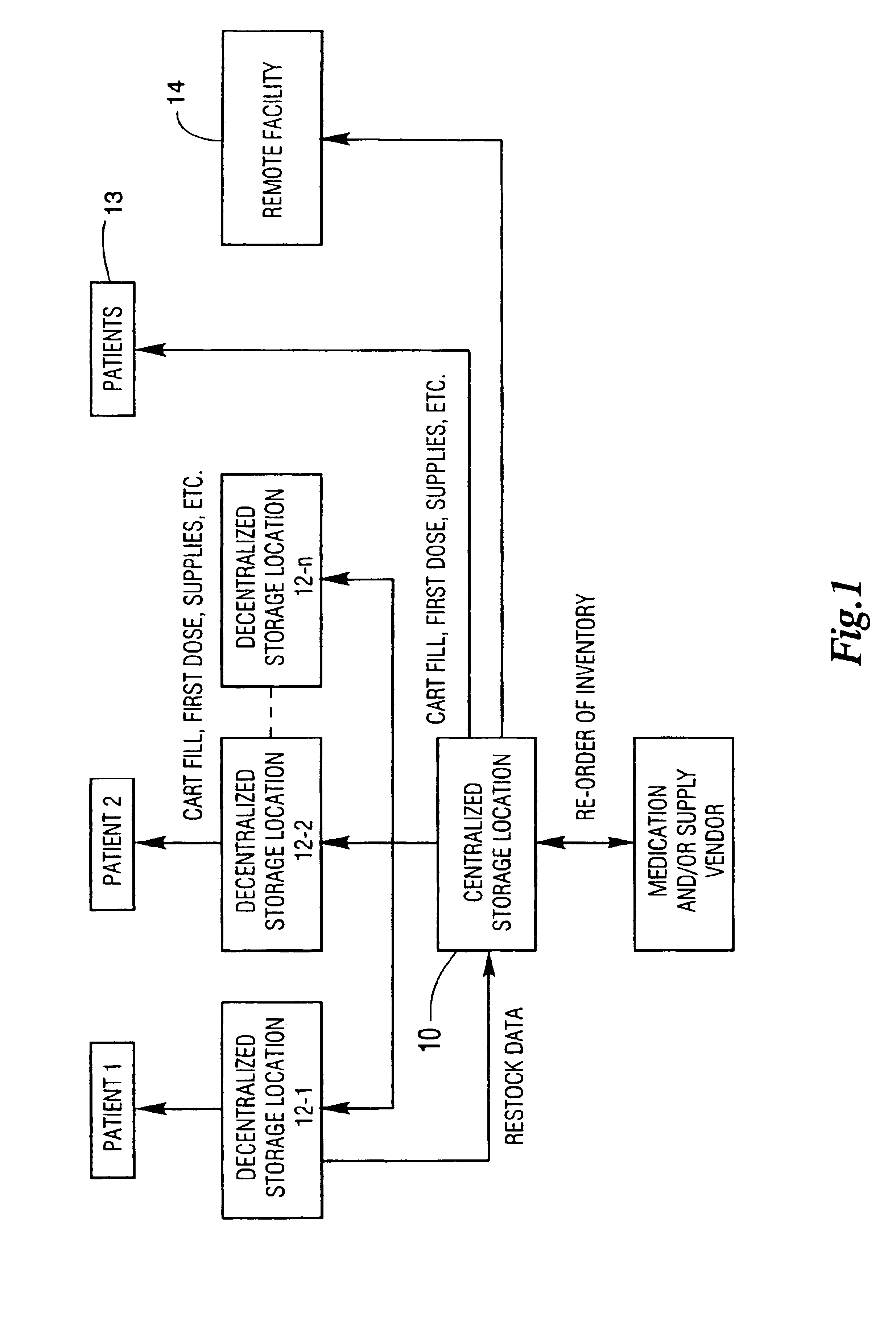
[0039]FIG. 1 is a diagram illustrating the relationship between a centralized storage location 10 and various inventory destinations, including a plurality of decentralized storage locations 12-1, 12-2 through 12-n, patients 13, and a remote facility 14. Each of the decentralized storage locations 12-1 through 12-n is capable of dispensing items stored at the location. The items may include medications, controlled medical supplies, medical supplies or items of a nature consistent with the facility in which the system illustrated in FIG. 1 is located. Items may be dispensed directly from centralized storage location 10 to patients 13, or from the centralized storage location 10 to a remote facility 14. Data typically flows from the decentralized storage locations 12-1 through 12-n to the centralized storage location 10. In response to that data, items are typically moved from the central storage location 10 to the decentralized storage locations 12-1 through 12-n or to the remote fac...


PUM


Abstract

A drawer for use in a dispensing cabinet is comprised of a tray movable between an open position and a closed position. An insert, approximately the length of the tray, is carried by the tray and defines the volume of the drawer. A lockable or sealable lid is carried by the insert. A release mechanism is provided to connect the insert to the tray in a manner that allows the insert to be easily disconnected from the tray. Removal of the insert enables inserts to be swapped so that inserts from which inventory has been depleted can be replaced with stocked inserts. A dispensing cabinet and a method of restocking the cabinet are also disclosed.

Description

CROSS-REFERENCE TO RELATED APPLICATIONS[0001]The present invention is a divisional of U.S. application Ser. No. 09 / 998,515 entitled “Dispensing Cabinet with Unit Dose Dispensing Drawer” filed 30 Nov. 2001, now U.S. Pat. No. 6,785,589 and assigned to the same assignee as the present invention.BACKGROUND OF THE INVENTION[0002]1. Field of the Invention[0003]The present invention is directed to dispensing cabinets and, more particularly, to dispensing cabinets having drawers of the type which are opened and closed under the control of a computer to control access to the contents of the drawer.[0004]2. Description of the Background[0005]In large medical facilities, inventories of medical supplies are normally held in centralized storage locations or pharmacies which are often far removed from decentralized storage locations. It is at the decentralized storage locations, e.g. a nurses station, that dispenses for patients are typically performed. To facilitate dispensing of medications and...

Claims


Application Information

Patent Timeline
Patent Type & Authority Patents(United States)
IPC IPC(8): G06F17/00A61J7/00G06F19/00G07F11/62
CPCG06F19/3462G07F17/0092G07F11/62G16H20/13G16H40/67
Inventor EGGENBERGER, VICTORYOUNG, KIRKBOWERS, ALLEN
Owner OMNICELL
Why Eureka
Try Eureka