Electromagnetic connecting device for high voltage and large current

a technology of electromagnetic connection and large current, which is applied in the direction of transformer/inductance details, electrical equipment, inductance, etc., can solve the problems of inability to accurately finish the shape, the edge cannot be formed precisely, and the shape cannot be easily pressed using a conventional tandem or transfer press

Inactive Publication Date: 2002-11-21
IHI CORP
View PDF5 Cites 44 Cited by
  • Summary
  • Abstract
  • Description
  • Claims
  • Application Information

AI Technical Summary

Problems solved by technology

However, there are some pressed shapes that cannot be easily pressed using a conventional tandem or transfer press.
For instance, when a component, some part of which has a complicated shape, e.g. the handle portion of a door panel is pressed and formed, the edge cannot be formed precisely even with a pressing process, and the shape cannot be accurately finished.
Therefore, when a high quality is particularly required, 2 or 3 processes are required, and as a result, a plurality of sets of upper and lower dies are needed, and a plurality of pressing processes must be provided, so that the production efficiency is low and the cost is high, which are practical problems.
In addition, there is a demand for aluminum material to be used to reduce the weight of a vehicle, however compared to steel sheets, aluminum has a large spring-back characteristic, therefore the shape cannot be finished precisely which is another problem in practice.
However, in a conventional connector, the conductors (bus bars etc.) are held in contact by mechanical forces such as by applying a tightening torque, so a problem of such a connector is that excessive time and labor are spent in mounting and removing bolts etc.
Also with a conventional connector that is detachable without loosening bolts, known in the prior art, there is a large loss in the connector due to the large current and the contact resistance, so this type of connector has the problem that the above-mentioned high-voltage, large-current pulses cannot be transmitted efficiently.
Furthermore, the high-voltage, large-current pulse transformer that transmits electric energy through the electromagnetic coupling cannot be dismantled because the primary and secondary circuits are fixed.

Method used


Image

  • Electromagnetic connecting device for high voltage and large current
  • Electromagnetic connecting device for high voltage and large current
  • Electromagnetic connecting device for high voltage and large current

Examples


Embodiment Construction

[0038] Preferred embodiments of the present invention are described below referring to drawings. When a part is shown in several drawings it is identified with the same reference number, and no duplicate description is given.

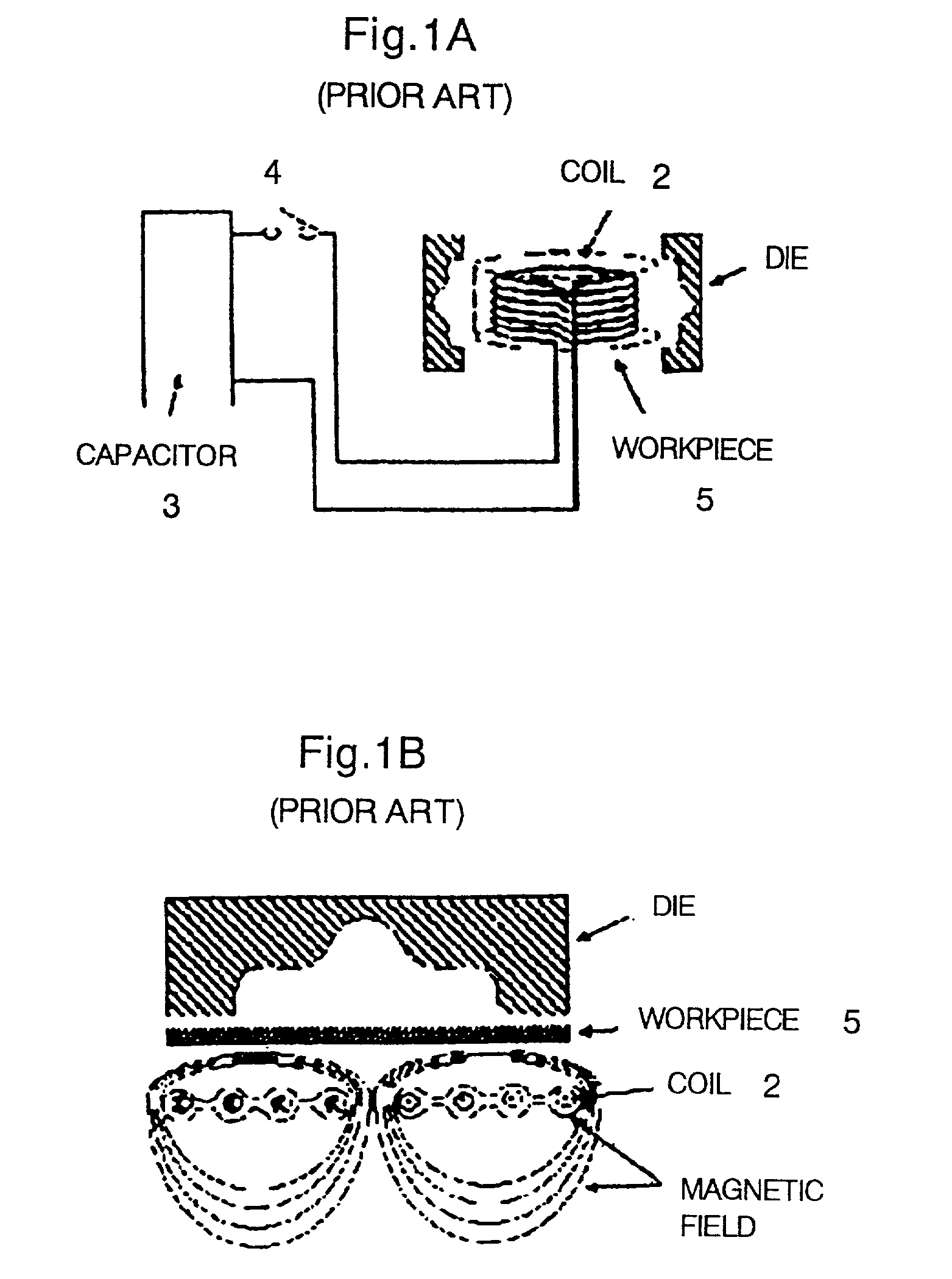
[0039] FIGS. 1A and 1B show the principles of electromagnetic forming, i.e. cylindrical forming and sheet forming, respectively. The electromagnetic forming system is a method of processing a metal workpiece using the energy of a magnetic field, so an intense magnetic field is required to produce a sufficient processing force. For this purpose, a large-capacitance, high-voltage capacitor 3 (capacitor bank) discharges current into a magnetic forming coil 2 to produce an instantaneous intense magnetic field which is used for forming.

[0040] More explicitly, the large-capacitance capacitor 3 stores energy at a high voltage of about 10 kV, for example, and by closing the discharge switch, the capacitor instantaneously outputs a large current (for instance, 150 kA, 30...


PUM

PropertyMeasurementUnit
frequencyaaaaaaaaaa
frequenciesaaaaaaaaaa

Abstract

The major components are a primary winding 12 connected to a high-voltage, a large-current power supply 1, a secondary winding 14 connected to an electromagnetic forming coil 2, and a magnetic core 16 for guiding the magnetic flux produced by the primary winding. The magnetic core 16 is composed of a primary core 16a on which the primary winding is wound and a secondary core 16b on which the secondary winding is wound. The primary core and the secondary core are magnetically connected together by putting them in contact or in close proximity. And the primary core and the secondary core are separeated each other when the connector is disconnected. Thus, current pulses at a high voltage (for instance, 10 kV) with a large current (for example, 100 kA or more) and a narrow pulse width (e.g., 30 musec or less) can be efficiently transmitted, and the connector can be easily attached and removed.

Description

[0001] 1. Technical field of the invention[0002] The present invention relates to an electromagnetic connecting device for use with high voltages and large currents, which is detachable without using contacts.[0003] 2. Description of the Prior Art[0004] Conventionally, a tandem press or transfer press is used to manufacture 3-dimensionally formed components with rather complicated shapes, such as automobile bodies or door panels. However, there are some pressed shapes that cannot be easily pressed using a conventional tandem or transfer press.[0005] For instance, when a component, some part of which has a complicated shape, e.g. the handle portion of a door panel is pressed and formed, the edge cannot be formed precisely even with a pressing process, and the shape cannot be accurately finished. Therefore, when a high quality is particularly required, 2 or 3 processes are required, and as a result, a plurality of sets of upper and lower dies are needed, and a plurality of pressing pr...

Claims


Application Information

Patent Timeline
Patent Type & Authority Applications(United States)
IPC IPC(8): H01F38/14
CPCH01F38/14
Inventor KOBAYASHI, YASUOMAJIMA, TAKASHISASAKI, YUUJI
Owner IHI CORP
Why Eureka
Try Eureka