Remote bolted flange connection apparatus and methods of operation thereof

a bolted flange and bolted technology, applied in mechanical equipment, sewer pipelines, pipe laying and repair, etc., can solve the problems of limited application of this method, lack of widespread acceptance of bolted flanges, and inability to use this important connection method in deepwater applications. , to achieve the effect of reducing the complexity of deployment and recovering the cost of tooling

Inactive Publication Date: 2005-06-30
ACERGY UK
View PDF10 Cites 44 Cited by
  • Summary
  • Abstract
  • Description
  • Claims
  • Application Information

AI Technical Summary

Benefits of technology

[0023] In the embodiment, said stud insertion tool is operable to engage a hole on the first flange using either a stud or equivalent body and, by rotating itself around the conduit axis, to rotate the first flange, thereby to align the holes in the first and second flanges. This avoids the need to deploy flange alignment tool and connection tooling sequentially, as in the original MATIS™ system.
[0024] To reduce the complexity of deployment, said stud loading tool may be carried on a first sub-frame while said nut running tool is carried on a second sub-frame, both sub-frames in turn being carried on a common frame for deployment as a single unit. Said common frame may comprise an inner frame and an outer frame, the stud insertion tool, nut running tool, stud storage means and (where provided) nut storage me

Problems solved by technology

In use, the application of this method is restricted because of the limited depth in which the diver can safely operate.
Accordingly, the use of this important connection method has to date been precluded from deepwater applications which extend beyond those depths where it is safe for divers to operate.
These lack the widespread acceptance of the simple bolted flange.
The cost of deploying such systems is therefore still quite great, especially as depths increase.
With the consumables set out in this flange pattern, complications arise when there is a fault with any of the nuts or bolts as the tooling cannot repl

Method used


Image

  • Remote bolted flange connection apparatus and methods of operation thereof
  • Remote bolted flange connection apparatus and methods of operation thereof
  • Remote bolted flange connection apparatus and methods of operation thereof

Examples


Embodiment Construction

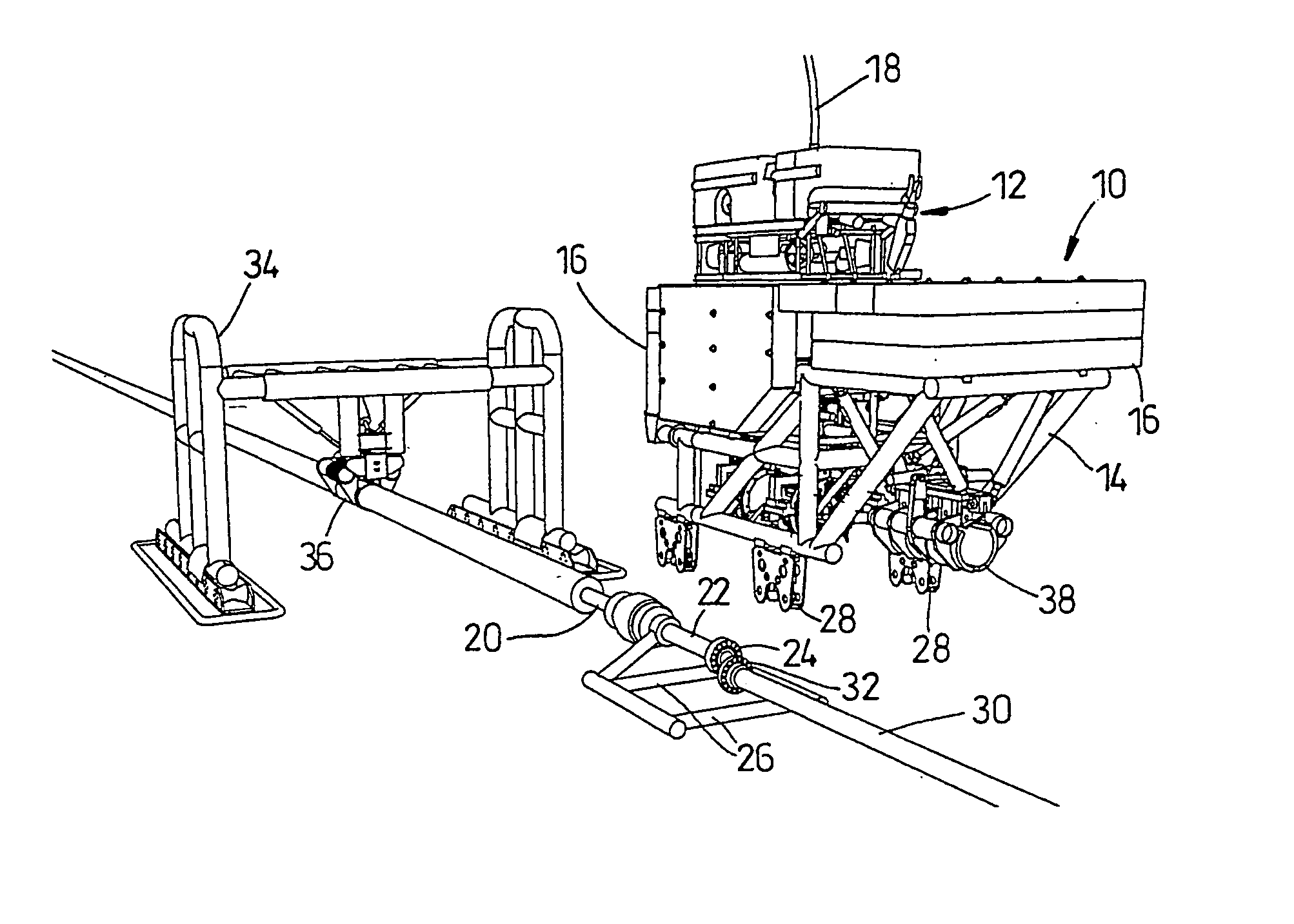
[0092] The bolted flange connection system to be described has been designed to make up standard ANSI and API flange joints for various pipeline tie-in situations, such as spool piece connection and flowline-tree connections. This provides the opportunity of utilising proven technology from shallow water into deepwater applications, without the need for divers and with the benefits of reduced costs and lead times, and increased system reliability. The system has been developed from the MATIS™ System described in the paper by West et al, mentioned in the introduction.

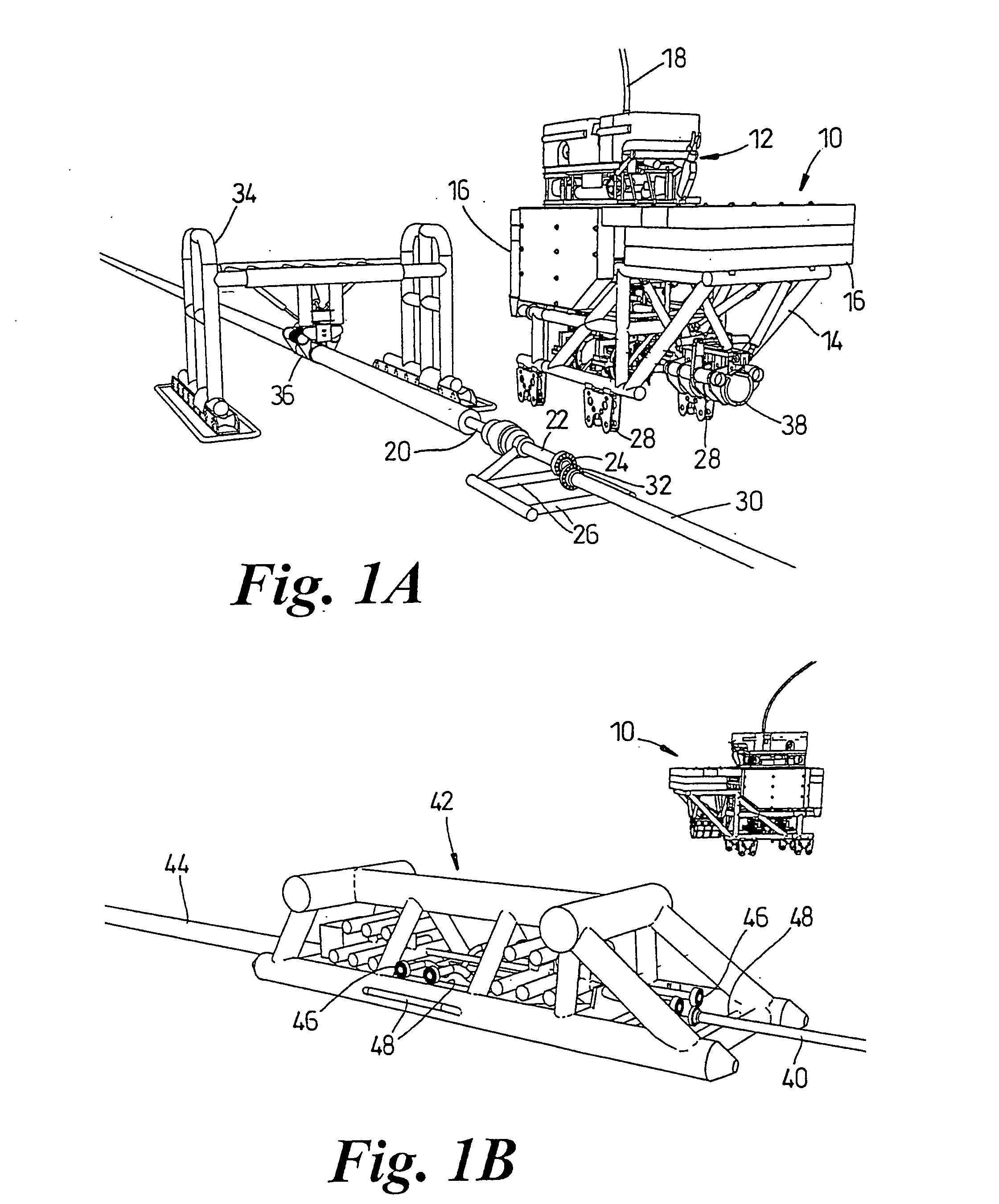
[0093]FIG. 1 shows a diver-less flange connection apparatus 10 approaching a work site under control of a remotely operated vehicle (ROV) 12. The apparatus is carried entirely within frame 14, so as to have very little weight when submerged. ROV 12 and apparatus 10 receive power and control signals via an umbilical cable 18.

[0094] At the work site shown in FIG. 1A, a pipeline repair is to be completed. A broken pipelin...


PUM


Abstract

A single-module deployable bolted flange connection apparatus (10) makes up standard flange joints (24, 32) for various pipeline tie-in situations, such as spool piece connection and flowline-tree connections, without the use of divers and auxiliary multiple pieces of equipment. An outer Flange Alignment Frame (FAF) (14), carries one or more claws (38) for grabbing the pipe/spool to provide flange alignment. The claws are suspended and driven by a novel arrangement of five hydraulic rams (412-420) A crash-resistant inner frame (148) houses complete connection tooling (150, 152 etc.) The tooling performs the final alignment steps, inserts the gasket and studs, applies the required tension, and connects the nuts. Studs and nuts are stored separately from the tooling in an indexed carousel, to permit multiple operations, reverse operations (disconnection), and re-work of failed steps, all without external intervention.

Description

FIELD OF THE INVENTION [0001] The present invention relates to a bolted flange connection apparatus and method. More specifically, it concerns an apparatus and method for the remote connection, and optionally disconnection, of the flanges of a sub-sea pipeline in a deepwater environment. BACKGROUND OF THE INVENTION [0002] Bolted flanges are by far the most widely used and cost effective method of connecting sub-sea pipelines in the oil and gas industry today. The widespread use of this method is largely due to the long-term performance and reliability of sub-sea flanges during the lifetime of the pipeline. Additionally, the level of confidence that pipeline operators have in the integrity of such a connection adds to its universal acceptance as the most appropriate method for connecting pipelines. [0003] Since the inception of this method of connection, the installation of bolted flanges in sub-sea environments has been performed manually by divers. In use, the application of this m...

Claims


Application Information

Patent Timeline
IPC IPC(8): B23P19/06F16L1/26
CPCF16L1/26B23P19/069
Inventor GILES, JOHN J.CAMPING, MICHAELWISHART, GRAHAM
Owner ACERGY UK
Why Eureka
Try Eureka