Electronic stethoscope system

a stethoscope and electronic technology, applied in the field of stethoscopes, can solve the problems of inconvenient use, inability to communicate in real time, and many systems are thus restricted to use, so as to simplify the design of the remote stethoscope uni

Inactive Publication Date: 2006-10-03
RNK PROD INC
View PDF23 Cites 136 Cited by
  • Summary
  • Abstract
  • Description
  • Claims
  • Application Information

AI Technical Summary

Benefits of technology

[0014]One novel feature of one embodiment of the present invention is the use in the stethoscope units of a low frequency boost to improve the low frequency response down to approximately 20 Hz. The low frequency boost may be implemented in different ways, such as: 1) in a transmitting section of the local stethoscope unit only (non-switchable), 2) in the transmitting section of the local stethoscope (non-switchable) and the receiving sections of the stethoscope units (switchable with a bell / diaphragm toggle switch), and 3) in the transmitting section of the local stethoscope (switchable) and the receiving sections of the stethoscope units (switchable with the bell / diaphragm toggle switch), where a reverse data channel provides the communications path for the bell / diaphragm switch command from the remote stethoscope unit to the local stethoscope unit. Hence, the present invention provides for boosted, very low auscultation frequency performance bandwidth and for enhanced the bell-diaphragm characteristics of a traditional stethoscope.
[0015]Another novel feature of one embodiment of the present invention is that the same stethoscope unit may be used as the local stethoscope unit and remote stethoscope unit. When the chest piece assembly is plugged into the local stethoscope unit, its presence is sensed and the local stethoscope unit automatically goes into its transmit mode. In transmit mode, the auscultation signal is sent by the local stethoscope unit over the data communications channel to the remote stethoscope so that a clinician at the remote stethoscope unit may hear the auscultation sounds. The absence of the chest piece assembly being plugged into the remote stethoscope unit causes the remote stethoscope unit to go into its receive mode to receive the auscultation signal from the data communications channel.
[0016]Another novel feature of one embodiment of the present invention is that it provides an efficient, low cost remote telephonic stethoscope system using an ADM / CVSD codec that passes high quality sound using a low bit rate for real-time use over a normal, bandwidth-limited telephone line, while having expanded high auscultation frequency coverage. In other words, the same low bit rate of 9.6 Kb / s of the prior art design is achieved, but this embodiment also achieves a greater frequency bandwidth for the auscultation signal.
[0019]Another novel feature of the one embodiment of the present invention is that a single clock frequency with appropriate dividers leading to each component of the stethoscope units may be used to drive both the ADM / CVSD and USART ICs so that the 7.68 Kb / s data rate is perfectly in synchronization with the 9.6 Kb / s data line rate. This eliminates the possibility of long term data over-runs or under-runs, thereby making the design of the remote stethoscope unit simpler.

Problems solved by technology

The techniques and equipment available in the prior art to accomplish this produce a digital signal with a data rate that significantly limits the frequency range of the auscultation signal that may be passed over normal telephone lines; hence, many systems are thus restricted to usage between facilities that have broadband communications channels.
Currently, most homes do not have broadband communications service.
This is not real-time and is awkward for the clinician and patient.

Method used


Image

  • Electronic stethoscope system
  • Electronic stethoscope system
  • Electronic stethoscope system

Examples


Embodiment Construction

[0023]In the following description, for purposes of explanation, numerous details are set forth in order to provide a thorough understanding of the disclosed embodiments of the present invention. However, it will be apparent to one skilled in the art that these specific details are not required in order to practice the disclosed embodiments of the present invention. In other instances, well-known electrical structures and circuits are shown in block diagram form in order not to obscure the disclosed embodiments of the present invention.

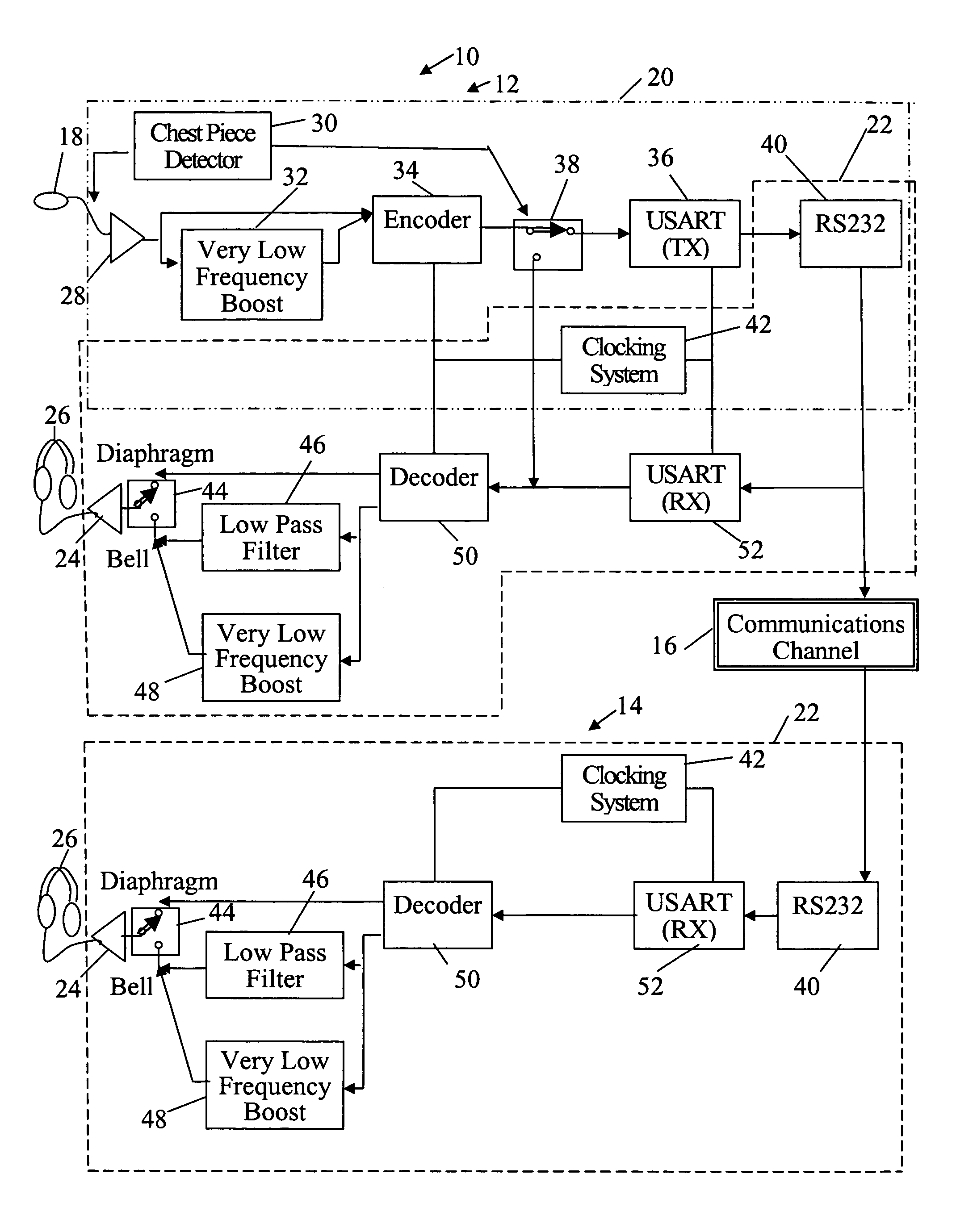
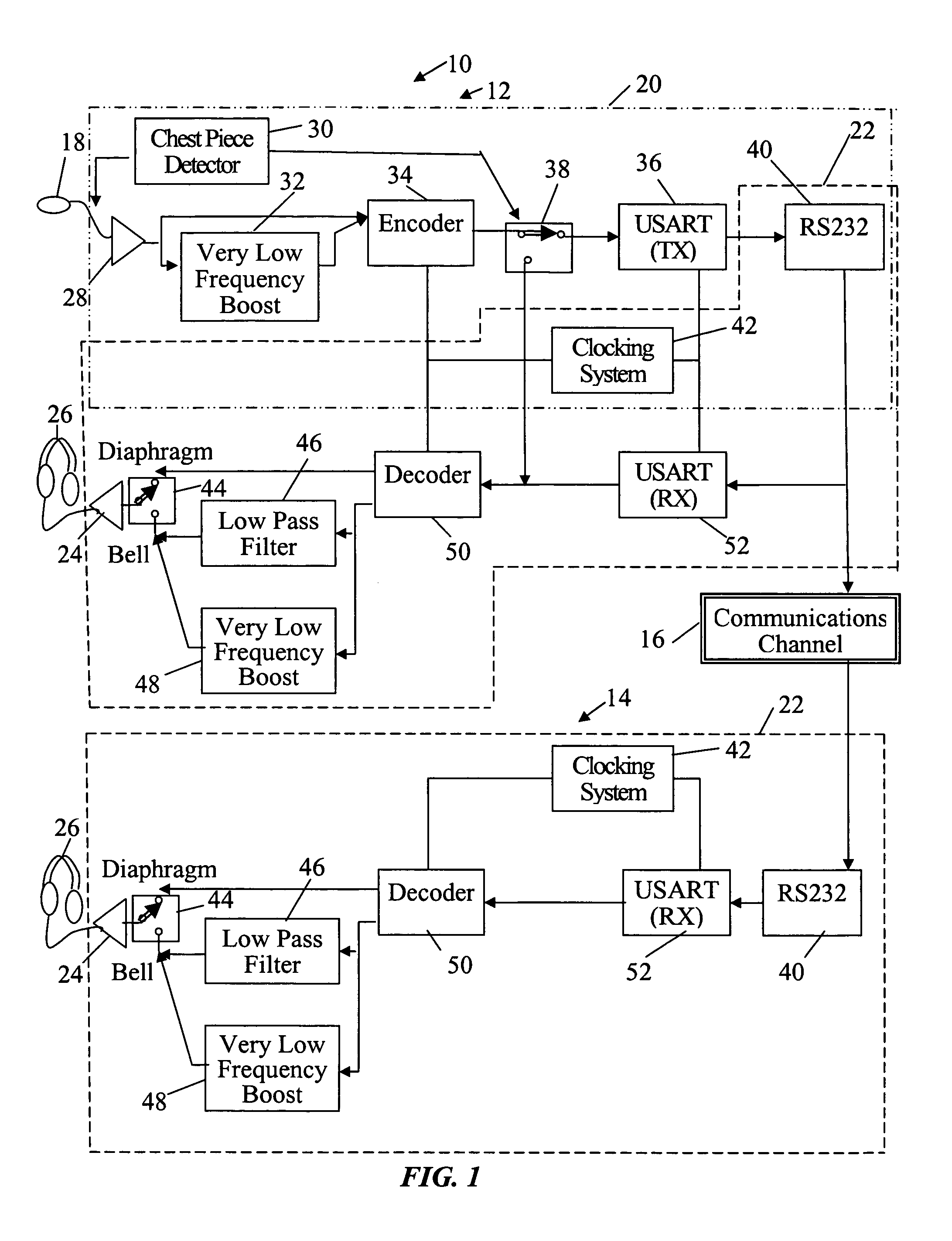
[0024]With reference to FIG. 1, a stethoscope system 10 is illustrated in one embodiment of the present invention. The stethoscope system 10 includes a local stethoscope unit 12 at a patient's location and a remote stethoscope unit 14 at a clinician's location connected over a data communications channel 16. In the preferred embodiment, the local stethoscope unit 12 and remote stethoscope unit 14 are identical in design, with the exception that a ches...


PUM


Abstract

In a local stethoscope unit, acoustic auscultation sounds picked up by the stethoscope chest piece assembly of a local stethoscope unit are converted to analog electrical signals and then converted to digital signals. The digital signals are conveyed to a data communications system, having data communications device and a data communication channel. The digital signals are transmitted over the digital communications system to a remote stethoscope receiving unit. The remote stethoscope unit converts the digital signals back to the original analog signals suitable for listening.

Description

BACKGROUND OF THE INVENTION[0001]1. Field of the Invention[0002]The present invention relates stethoscopes and in particular to coding and digitally transmitting auscultation sounds to a remote location where the signals are decoded and converted back to analog sounds for listening.[0003]2. Description of Related Art[0004]When a clinician examines a patient, the clinician typically will check the patient's vital signs. Key among the vital signs typically checked are the cardiovascular (heart) and respiratory (lung) sounds of the patient. Sounds coming from the body are referred to as auscultation sounds and a stethoscope is the medical device used to listen to a patient's auscultation sounds. A typical stethoscope will have a bell and diaphragm capability, where the bell position slightly enhances the lower frequency sounds of the beating heart and the diaphragm position is better at passing the higher frequencies, such as the breath sounds of the lungs.[0005]The clinician will plac...

Claims


Application Information

Patent Timeline
Patent Type & Authority Patents(United States)
IPC IPC(8): A61B7/00A61B7/04
CPCA61B7/045Y10S128/904
Inventor ABBRUSCATO, CHARLES R.
Owner RNK PROD INC
Why Eureka
Try Eureka