Needleless medical connector with expandable valve mechanism

a technology of valve mechanism and needleless connector, which is applied in the field of needleless connector employing a valve mechanism, can solve the problems of piercing of the septum, affecting the flow rate of internal cannula or spike, and undesirable negative bolus effect,

Inactive Publication Date: 2009-03-03
CAREFUSION 303 INC
View PDF22 Cites 150 Cited by
  • Summary
  • Abstract
  • Description
  • Claims
  • Application Information

AI Technical Summary

Benefits of technology

[0014]By providing a flex-tube assembly having an internal volume when compressed, e.g., activated by the insertion of a blunt cannula, that is at least as great as the internal volume when the flex-tube assembly is uncompressed, the possibility of a partial vacuum forming within the fluid path defined by the flex-tube assembly upon removal of the blunt cannula is essentially eliminated and instead, a positive-bolus effect or a no-bolus effect is provided. Thus, fluid is prevented from being drawn into the connector through the outlet port upon removal of the blunt cannula.

Problems solved by technology

A negative-bolus effect is undesirable in that the partial vacuum created within the connector may draw fluid from the IV tubing.
However, both of these approaches are undesirable in that the operator must remember to perform an additional step during removal of the syringe or other device from the connector rather than the steps being taken automatically by the connector.
A disadvantage of typical connectors having an internal cannula or spike is a lower fluid-flow rate.
Additionally, it has been noted that with the connector design having a fixedly-mounted internal spike and a movable septum that is pierced by that spike to permit fluid flow, such pierced septum may be damaged with multiple uses and a leaking connector may result.
This displacement of fluid may fill the partial vacuum being formed by the deactuation of the valve mechanism and thus reduce the possibility of fluid being drawn into the connector.
First, during periods of nonuse, residual fluid left within the collapsed reservoir is likely to dry and adhere to the leaf spring.
This may cause particulate to enter the fluid path during subsequent actuation or may even prevent the reservoir from expanding during subsequent actuation.
Second, the connector employs a complex two-part valve mechanism that requires an internal cannula for actuation and deactuation.
The complexity of this device lends itself to manufacturing difficulties and increased manufacturing costs.
Third, during actuation of the valve mechanism, the leaves of the rigid spring leaf may cut through the body and cause a leak.

Method used


Image

  • Needleless medical connector with expandable valve mechanism
  • Needleless medical connector with expandable valve mechanism
  • Needleless medical connector with expandable valve mechanism

Examples


Embodiment Construction

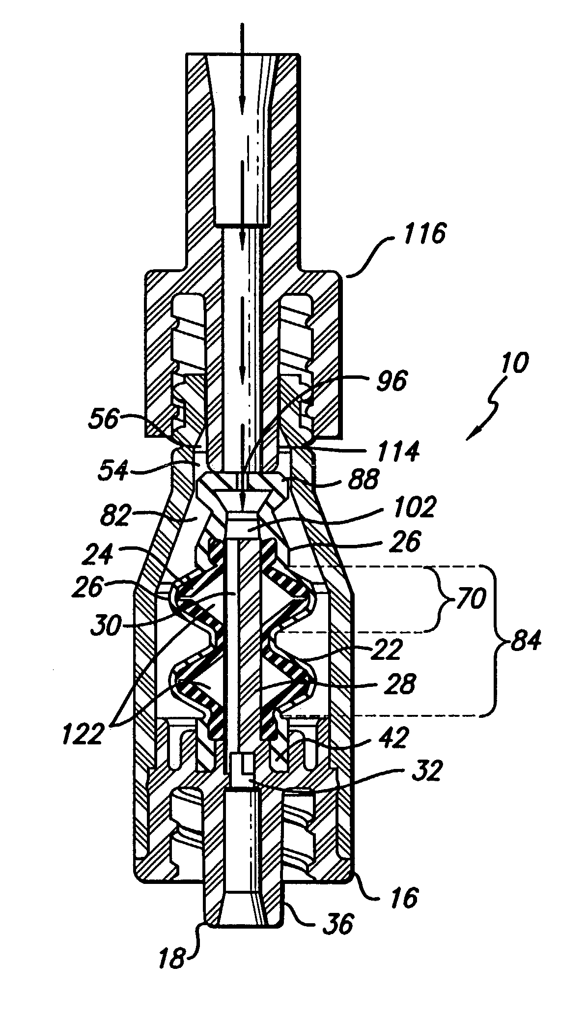
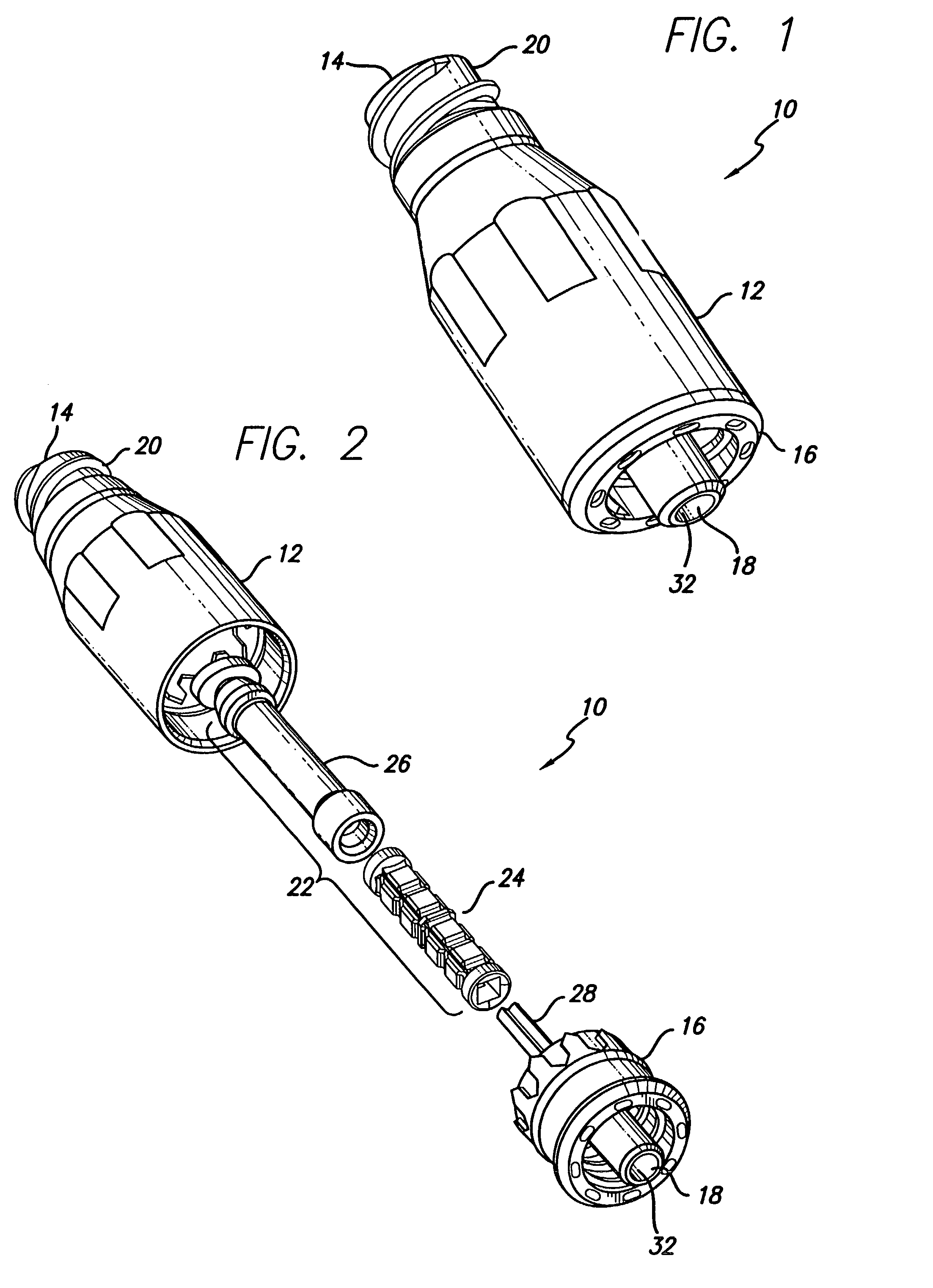
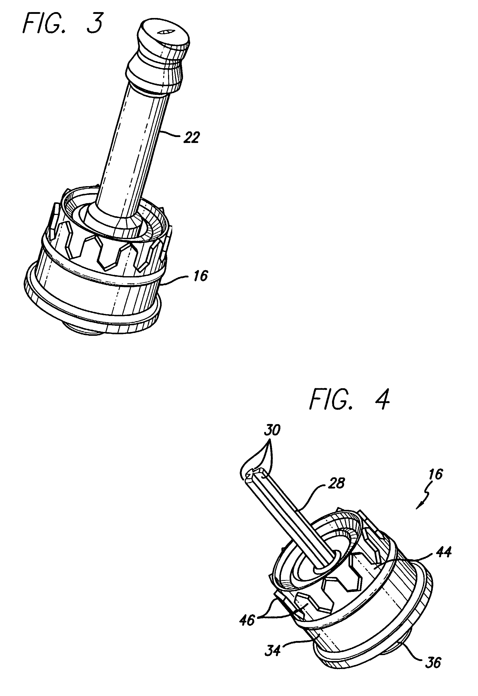
[0077]Referring now to the drawings in which like numerals refer to like or corresponding elements among the several figures, there is illustrated in FIGS. 1, 16 and 21 several medical connectors that include a needleless valve embodying aspects of the invention. These particular connector configurations are for illustration purposes only. The subject needleless valve can be embodied in any of a variety of connectors including, but not limited to, Y-connectors, J-loops, T-Connectors, Tri-connectors, PRN adapters, slip Luers, tubing engagement devices, access pins, vail adapters, blood tube adapters, bag access pins, and vented adapters.

[0078]As is shown in FIGS. 1 and 2, the connector 10 comprises a valve body 12 having an inlet port 14. The connector 10 further includes a male Luer-lock insert 16 terminating in an outlet port 18. The valve body 12 and the male Luer-lock insert form a connector housing. The portion of the valve body 12 near the inlet port 14 includes a Luer adapter ...


PUM

PropertyMeasurementUnit
volumeaaaaaaaaaa
thicknessaaaaaaaaaa
thicknessaaaaaaaaaa

Abstract

A needleless connector for medical use, adapted to facilitate the flow of fluid therethrough, includes a housing having an inlet port and an outlet port. The connector also includes a flex-tube assembly defining a fluid path between the inlet port and the outlet port. The flex-tube assembly is movable between uncompressed and compressed states. The flex-tube assembly has a first internal volume when in the uncompressed state and a second internal volume, greater than or substantially equal to the first internal volume, when in the compressed state.

Description

[0001]This is a division of application Ser. No. 09 / 361,543 filed Jul. 27, 1999 now U.S. Pat. No. 6,706,022.BACKGROUND OF THE INVENTION[0002]The invention relates generally to medical connectors of the type used in the handling and administration of parenteral fluids, and more particularly, to a needleless connector employing a valve mechanism that compensates for negative fluid displacement, i.e., drawing of fluid into the outlet end of a connector, during deactuation of the valve.[0003]Within this specification the terms, “negative-bolus effect,”“positive-bolus effect,” and “no-bolus effect” are used to describe the operating characteristics of medical connectors during deactuation of the valve mechanisms contained within the connectors. Negative-bolus effect describes the condition during which fluid is drawn into the connector during deactuation. Positive-bolus effect describes the condition during which fluid is flushed out of the connector during deactuation. No-bolus effect d...

Claims


Application Information

Patent Timeline
Patent Type & Authority Patents(United States)
IPC IPC(8): A61M5/00A61M39/02A61L2/16A61M39/04A61M39/10A61M39/16A61M39/22A61M39/26
CPCA61M39/26A61M2039/263
Inventor LEINSING, KARL R.MOSLER, THEODORE J.
Owner CAREFUSION 303 INC
Why Eureka
Try Eureka