Electric control and supply system

a technology of electric control and supply system, applied in the direction of valve operating means/release devices, wellbore/well accessories, sealing/packing, etc., can solve the problems of large hydraulic equipment, such as pumps at the surface, large hydraulic equipment, and occupying a significant amount of space on the platform or vessel, etc., to achieve high and stable voltage, eliminate hydraulic fluid, and respond quickly

Inactive Publication Date: 2005-02-10
ONESUBSEA IP UK LTD
View PDF98 Cites 178 Cited by
  • Summary
  • Abstract
  • Description
  • Claims
  • Application Information

AI Technical Summary

Benefits of technology

[0029] According to the invention, another advantage arises in that voltage frequencies can be modulated onto the direct voltage transmitted over the umbilical in a simple manner for data transmission. This can especially take place in that the electric supply and control assembly and the control and actuation assembly each exhibit at least one data modulation device. In at least some embodiments, the data modulation devices used in the control and actuating assembly may be disposed after the DC / DC or DC / AC converter components.
[0030] In summary, the system offers many advantages, such as quick response, elimination of hydraulic fluid, no dumping of fluid to sea (environmentally friendly) and the ability to perform real time diagnostics on the actuators, valves and chokes. At the surface the requirement for a hydraulic power unit is eliminated and the surface equipment is generally more compact.
[0031] It is therefore the object of the present invention to improve a power supply system so that it is possible to provide a high and stable voltage, even in the case of high power requirements, in a reliable manner and at a reasonable price, without any additional components for e.g. heat dissipation being necessary. The object of the present invention is to provide a power supply system to remote (e.g., subsea) electrical devices so that with small constructional efforts and with low costs, the energy supply to the remote electrical device is guaranteed over great distances. Additionally, the power supply system is stable, efficient and redundant.
[0032] It should also be pointed out that, due to the DC voltage transmitted to the electric devices, thin line (cross-sections) umbilical conductors are possible especially when a coaxial cable is used as the umbilical; these thin line umbilicals permit a substantial reduction of the cable connection costs. In particular, when the distances to the electric devices are in the kilometer range (e.g., 50 kilometers) and when the coaxial cable can simultaneously be used for transmitting data as well, a substantial amount of costs will be saved.
[0033] Expensive capacitors, such as electrolytic filter capacitors, are no longer necessary for smoothing the DC voltage on the output side. In addition, power factor correction can take place directly at the location of the control and actuating assembly. For example, a suitable means for effecting this correction can be included in the DC / DC or DC / AC converter components or rather in the integrated circuit thereof. Additionally, high frequency clocking of the DC / DC or DC / AC converter components simultaneously guarantees that the DC voltage on the input side is sampled in full width, whereby a high efficiency is obtained.

Problems solved by technology

However, hydraulic supply lines are large and expensive.
Further, hydraulic equipment, such as pumps at the surface, are large and take up a significant amount of space on the platform or vessel.
One disadvantage with prior art control and supply systems, such as shown in FIG. 1(a), is that a costly subsea cable is necessary.
In addition, data lines are required, such that the subsea cable must have a substantial diameter, and thus be very costly.
Furthermore, with the previously described prior art control and supply system, the overall system only has an output power efficiency of 27%.
Such correction devices are very complex and normally quite expensive and consist of capacitors or similar devices.
If a high voltage is present on the input side, a corresponding conversion into another voltage is difficult as a rule because corresponding components of the converting device do not show a sufficiently high breakdown strength.
Moreover, in the case of a high power to be transmitted, the heat developed in the converting device may be considerable even if the power loss is only 10 or 20%.
This makes the converting device more expensive and also larger due to the additional cooling means.
Components having dielectric strengths of more than 1000V, e.g. 3000 or 6000V, are, however, not available or they can hardly be realized technically.
If such a converter is nevertheless suitable for such high DC voltages, the whole system will collapse if the converter fails to operate.
In addition, even if the efficiency is comparatively high, the converting device will have a dissipation power that produces a substantial amount of heat comparatively locally.
This amount of heat may destroy certain components of the converting device.
In order to avoid such destruction, complicated cooling systems are required which entail high costs.

Method used


Image

  • Electric control and supply system
  • Electric control and supply system
  • Electric control and supply system

Examples


Embodiment Construction

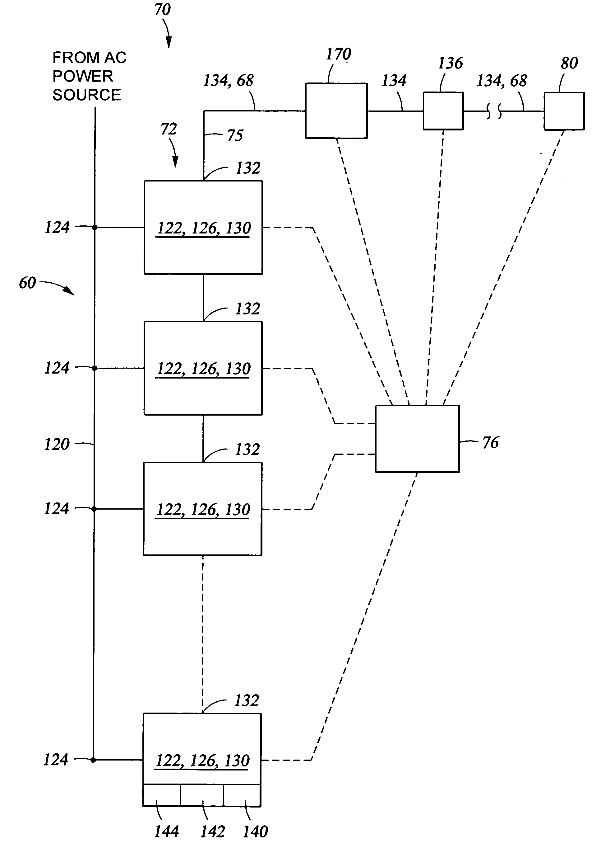
[0020] An electric control and supply system comprises a supply and control assembly at a first location and a control and actuating assembly at a remote location associated with one or more remote electrical devices. An umbilical extends between and connects the supply and control assembly with the control and actuating assembly for supplying a voltage to the control and actuating assembly. The supply and control assembly at the first location includes an AC voltage source coupled to an AC / DC voltage converter. The AC / DC voltage converter converts an AC voltage from the AC voltage source to a high DC voltage output at the first location. The AC / DC voltage converter comprises a plurality of AC / DC voltage converter components which, on the input side thereof, are connected in parallel with the AC voltage source and which, on the output side thereof, are connected serially to the umbilical. The umbilical extends to the control and actuating assembly and associated remote electrical de...


PUM


Abstract

A system supplies electrical power to a remote electrical device. The system includes an AC/DC voltage converter coupled to the AC voltage source for converting an AC voltage from the AC voltage source to a high DC voltage output at a first location. The AC/DC voltage converter comprises a plurality of AC/DC voltage converter components which, on the input side thereof, are connected in parallel with the AC voltage source and which, on the output side thereof, are connected serially to an electric conductor. The electric conductor extends to a plurality of voltage converters at a remote location having inputs connected serially to the electrical conductor and having outputs providing an appropriate voltage to the electrical device, the plurality of voltage converters converting the high DC voltage to either a lower DC voltage or an alternating voyage without a cooling mechanism that would otherwise be needed when less than the plurality of voltage converters are implemented to convert the high DC voltage to the lower DC voltage or alternating voltage.

Description

CROSS-REFERENCE TO RELATED APPLICATIONS [0001] The present application is a continuation-in-part application of each of the following applications: U.S. patent application Ser. No. 10 / 415,510, filed Apr. 29, 2003 and entitled Control and Supply System, which claims the benefit of PCT application PCT / EP01 / 12547 filed Oct. 30, 2001, which claims the priority of DE 200 18 560.8 filed Oct. 30, 2000 (1600-08400; OTE-030339); U.S. patent application Ser. No. 10 / 489,573 filed Mar. 12, 2004 and entitled Universal Power Supply System, which claims the benefit of PCT / EP02 / 10471 filed Sep. 18, 2002, which claims the priority of DE 201 15 471.9 filed Sep. 19, 2001 (1600-09300; OTE-030452); U.S. patent application Ser. No. 10 / 489,583 filed Mar. 12, 2004 and entitled Universal Power Supply System, which claims the benefit of PCT / EP02 / 10468 filed Sep. 18, 2002, which claims the priority of DE 201 15 473.0 filed Sep. 19, 2001 (1600-09500; OTE-030454); U.S. patent application Ser. No. 10 / 489,453 fil...

Claims


Application Information

Patent Timeline
Patent Type & Authority Applications(United States)
IPC IPC(8): F16K31/04F16K31/05F16K31/12F16K37/00H02J1/06H02M1/00H02M7/217
CPCE21B33/0355Y02E60/60F16K31/046F16K31/047H02J1/00H02J1/06H02J3/36H02J13/0024H02M7/217H02M2001/007H02M2001/0074H02M2001/0077F16K37/0083H02M7/04H02P5/68F16K31/041H02J13/00009H02M1/007H02M1/0074H02M1/0077H02J13/00017Y04S40/121Y04S40/124Y02E60/00
Inventor BIESTER, KLAUSKUNOW, PETERLENZ, NORBERT
Owner ONESUBSEA IP UK LTD
Why Eureka
Try Eureka