Fluidized particle abrasion device with precision control

a technology of fluidized particles and abrasives, which is applied in the direction of manufacturing tools, transportation and packaging, packaging, etc., can solve the problems of inability to achieve repeatability, difficulty in achieving precision, and difficulty in getting abrasive powders out of storage chambers into air streams in the precision rang

Active Publication Date: 2015-01-20
CRYSTAL MARK
View PDF45 Cites 33 Cited by
  • Summary
  • Abstract
  • Description
  • Claims
  • Application Information

AI Technical Summary

Problems solved by technology

However, fine abrasive powders and surface conditioning media in the 10 to 100 micron range used in these systems do not like to flow easily or consistently!
Getting them out of a storage chamber into an air stream in a precision, consistent volume has been problematic.
Results are sporadic and lacks repeatability and are further complicated when finer particles, (below 50 micron) are required.
This scheme offers a refinement but the powder flow is not independent of air pressure and not adjustable.
Furthermore, when changing over from one abrasive type to another, it may be necessary to change the internal orifice in the bottom of the powder chamber a task that can take several minutes.
Although a big step forward in powder flow flexibility, repeatability and consistency the downside for cycles of a short duration (stop and go) is a puff of abrasive at the start of each cycle caused by a venturi like effect when a burst of powder has been sucked into the air stream.
Also after the unit has been off for a time the first cycle presents a burst of powder, because due to gravity, abrasive has sifted down through the orifice plate.
While eliminating the gravity powder burst problem this design has an issue with abrasive cascading over the rim of the bowl feed chamber into the outer chamber and eventually damping down the vibrator coil within the outer pressure chamber.
There is also an issue with the fact that in use the coil heats up and causes the flow rate to fluctuate.
Furthermore the vibrator amplitude and hence the flow rate is not easily adjusted.
While offering fairly consistent flow rates the downside of this approach is the fact that the pneumatic ball bearing race used to agitate the abrasive powder can tax a compressor as it uses considerable amount of air.
As described above each of these approaches work to a certain degree but each has its inherent weaknesses.

Method used


Image

  • Fluidized particle abrasion device with precision control
  • Fluidized particle abrasion device with precision control
  • Fluidized particle abrasion device with precision control

Examples


Embodiment Construction

[0027]The following discussion describes in detail one embodiment of the invention and several variations of that embodiment. This discussion should not be construed, however, as limiting the invention to those particular embodiments. Practitioners skilled in the art will recognize numerous other embodiments as well.

Definitions

[0028]As used herein, the following terms and variations thereof have the meanings given below, unless a different meaning is clearly intended by the context in which such term is used.

[0029]The terms “a,”“an,” and “the” and similar referents used herein are to be construed to cover both the singular and the plural unless their usage in context indicates otherwise.

[0030]As used in this disclosure, the term “comprise” and variations of the term, such as “comprising” and “comprises,” are not intended to exclude other additives, components, integers, ingredients or steps.

The Invention

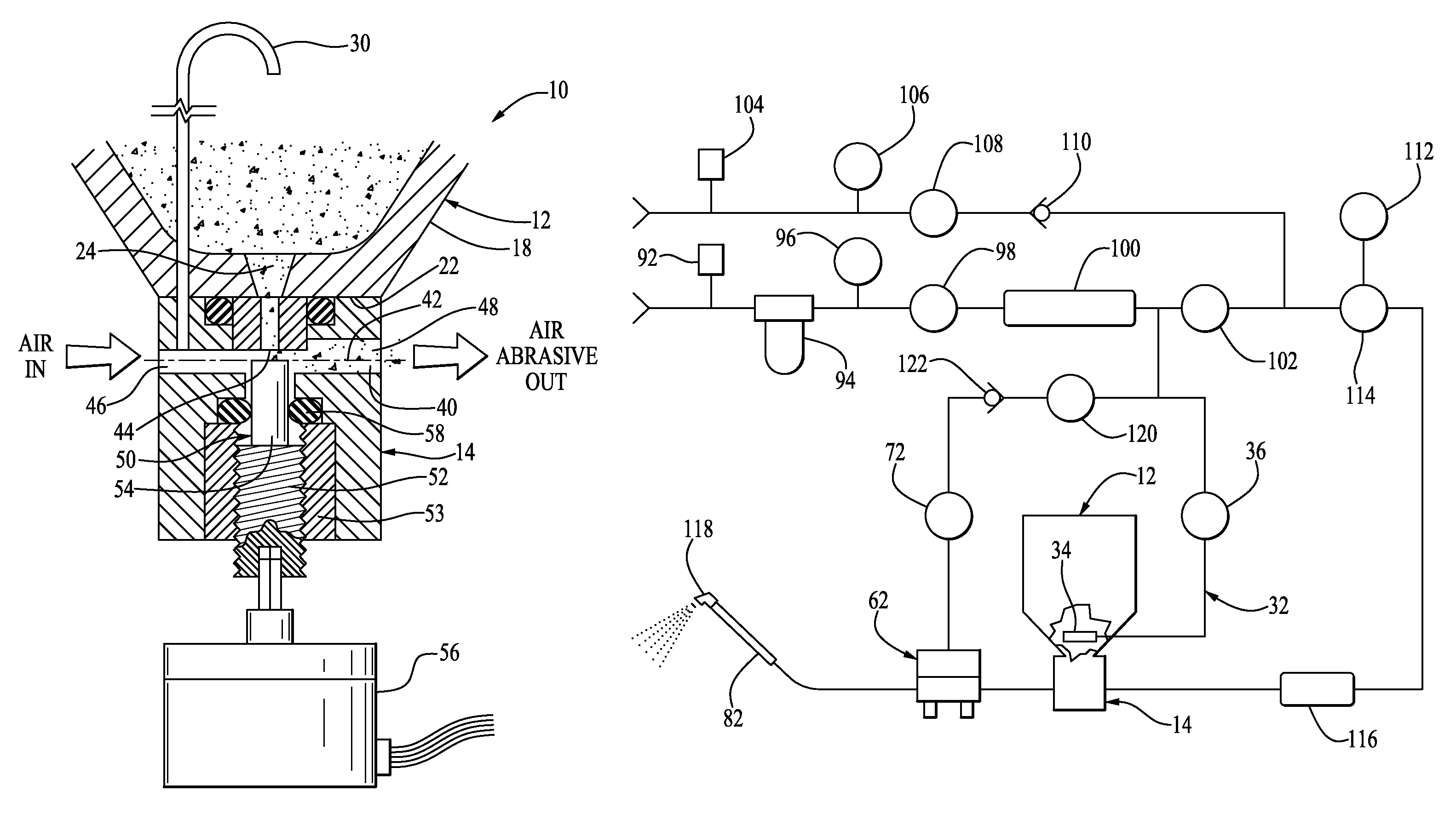
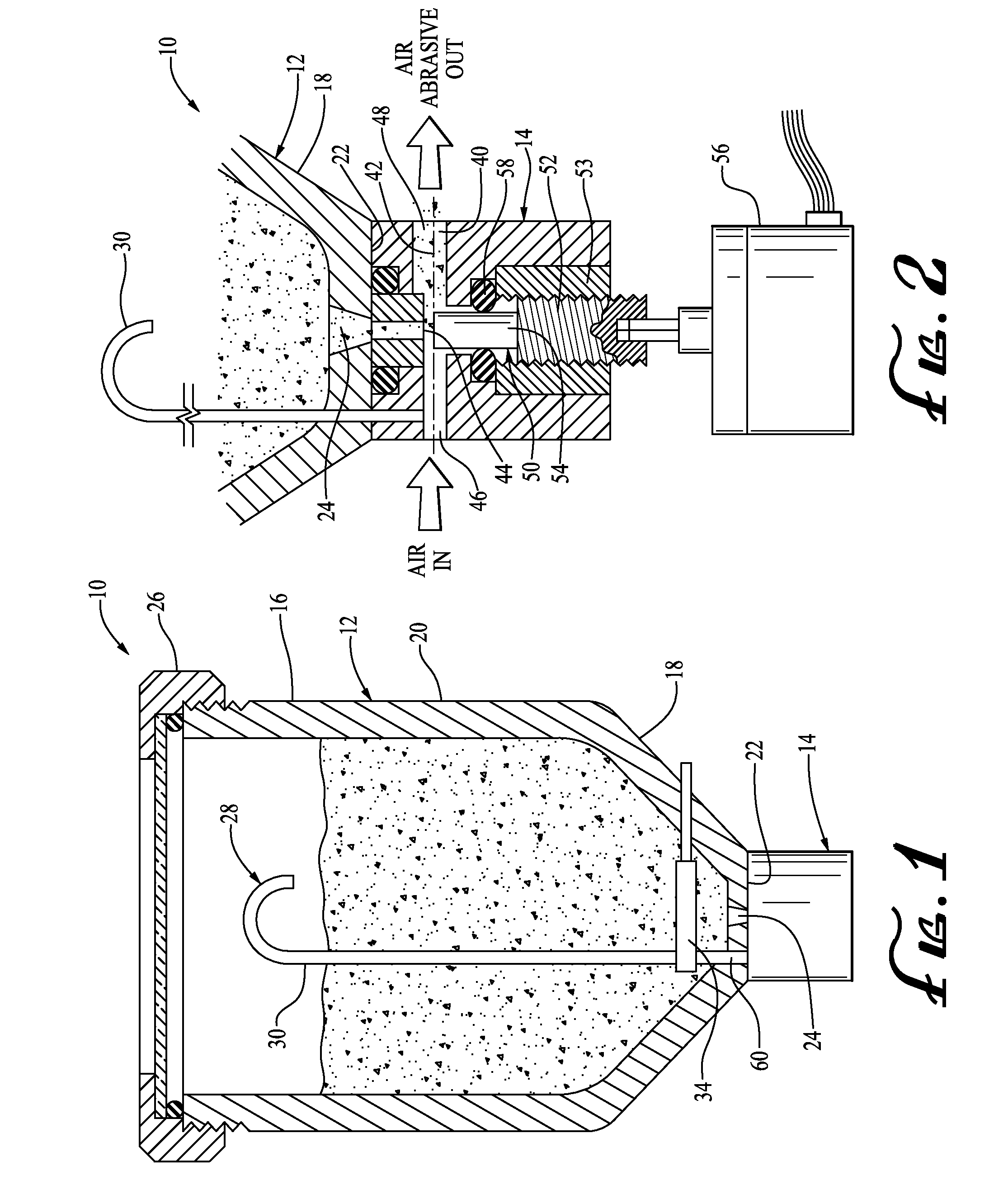
[0031]The invention is a portable fluidized particle abrasion device 10 for disp...


PUM


Abstract

A portable air abrasion device has a dispensing chamber and a flow valve for controlling the flow rate from the dispensing chamber. The flow valve includes a fluid flow chamber for receiving granular materials exiting the dispensing chamber. The fluid flow chamber has a granular materials inlet port, a fluid flow inlet port for receiving the flow of a fluid to the fluid flow chamber and a fluidized granular material exit port for dispensing a fluidized mixture of the granular material away from the fluid flow chamber. The fluid flow chamber also has a flow regulator employing a lead screw to control the flow of fluidized granular material through the fluidized granular material exit port.

Description

RELATED APPLICATION[0001]This application claims priority from U.S. Patent Application Ser. No. 61 / 839,491, entitled “Portable Air Abrasion Device With Precision Control Means,” filed Jun. 26, 2013 and U.S. Patent Application Serial No. 61 / 818,161, entitled “Flow Facilitator,” filed May 1, 2013, the entirety of both of which is incorporated herein by reference.FIELD OF THE INVENTION[0002]This invention relates generally to fluidized particle abrasion devices.BACKGROUND OF THE INVENTION[0003]In its most primitive form “sandblasting” can be accomplished by simply gravity feeding an abrasive media such as sand from a hopper with a hole in the bottom into a pressurized air stream. A slightly more sophisticated version of this is to use a pressurized powder tank instead of a hopper. This combination of pressure and gravity allows for a more consistent flow of the media. A simple metering orifice at the nozzle tip also helps with consistent delivery. These crude forms of abrasive blasting...

Claims


Application Information

Patent Timeline
Patent Type & Authority Patents(United States)
IPC IPC(8): B65G53/46
CPCB24C9/00B24C7/0053B05B7/1404B05B7/1486B65G53/14B65G53/40
Inventor STUTZ, JR., WILLIAM H.SWAN, JAWN P.SWAN, KEITH D.SWAN, E. MICHAELQUINTUS, JOHN J.
Owner CRYSTAL MARK
Why Eureka
Try Eureka