Cutting insert, cutting tool, and method of manufacturing machined product using them

a cutting tool and cutting insert technology, applied in the field of cutting tools and cutting inserts, can solve the problems of difficult to ensure a sufficient clearance angle between the flank surface and the workpiece, and the risk of early wear so as to increase the thickness of the cutting insert, reduce the risk of cutting, and ensure the clearance angl

US8979440B2Active Publication Date: 2015-03-17KYOCERA CORP
28 Cites 7 Cited by

Patent Information

Authority / Receiving Office
US · United States
Patent Type
Patents(United States)
Current Assignee / Owner
Publication Date
2015-03-17

Smart Images

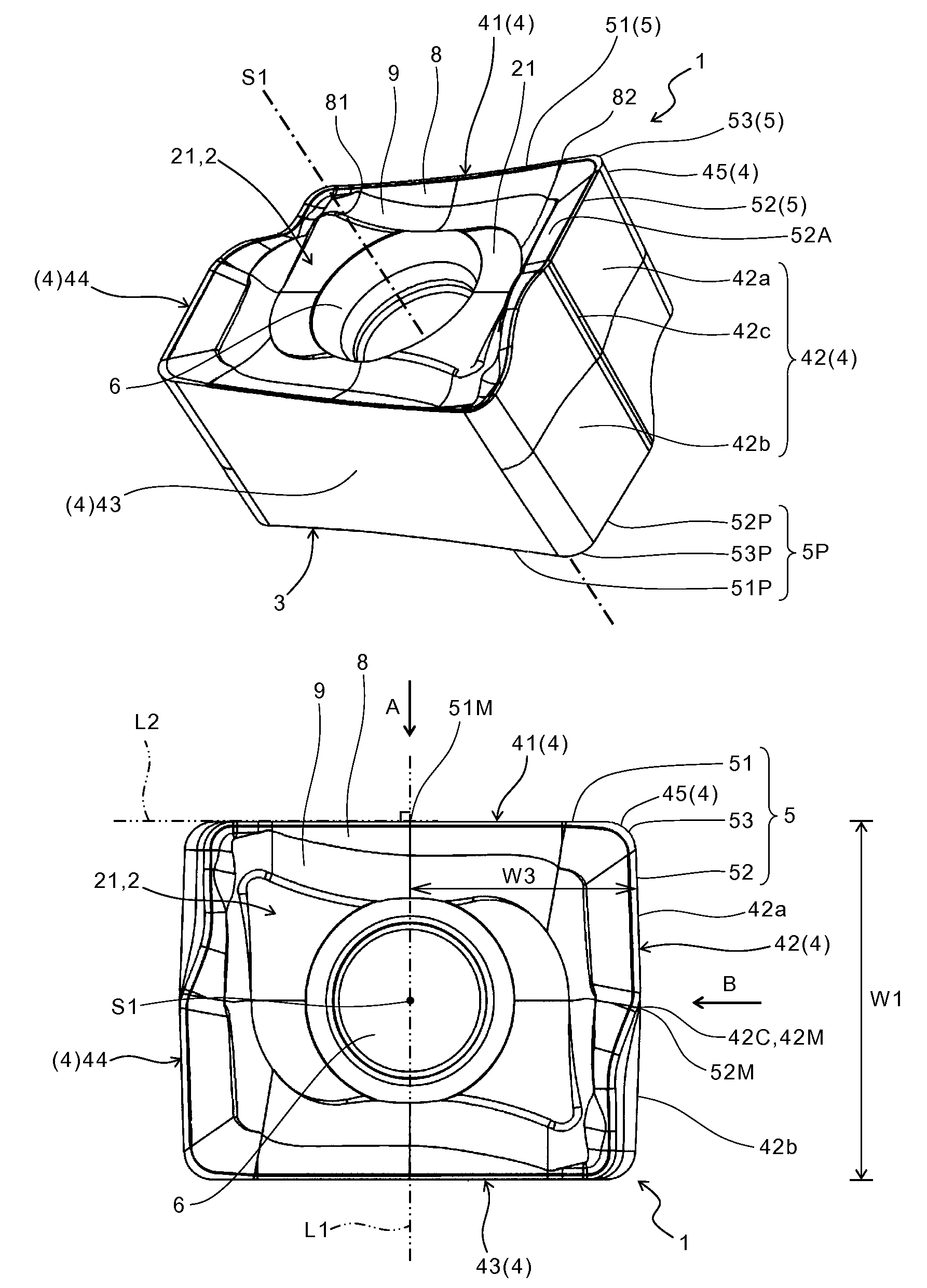
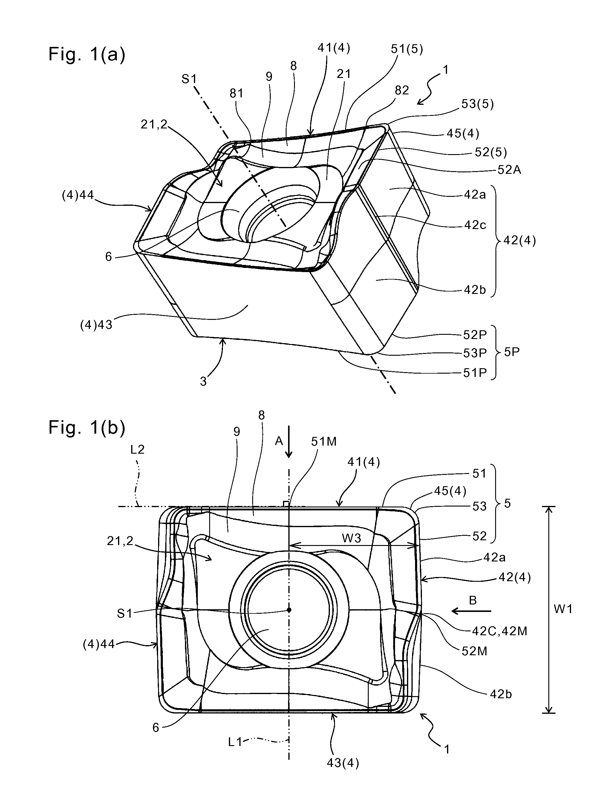
  • Figure 1
    Figure 1
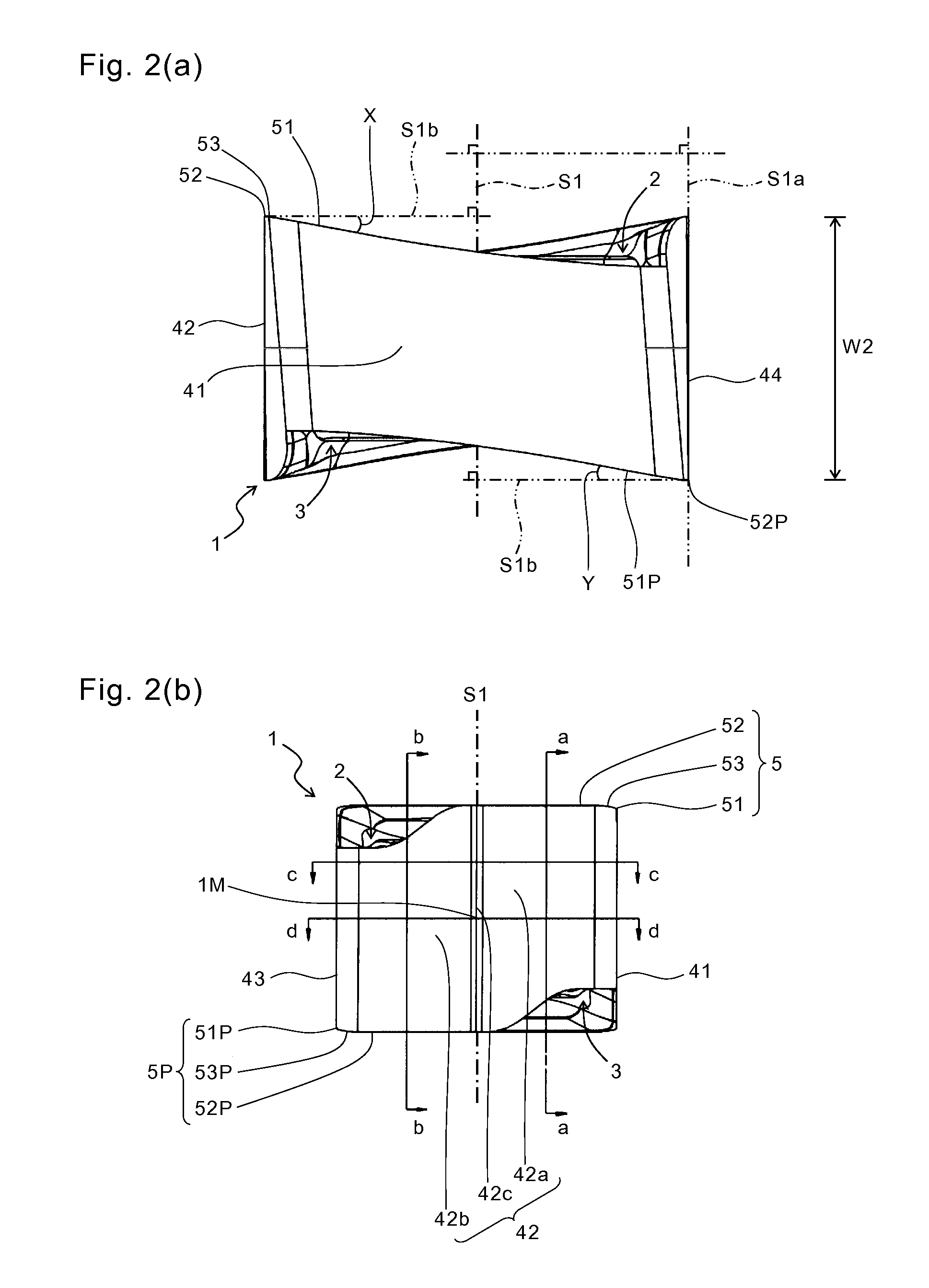
  • Figure 2
    Figure 2
  • Figure 3
    Figure 3
Patent Text Reader

Abstract

A cutting insert includes an upper surface; a lower surface; a side surface which is connected to each of the upper surface and the lower surface and includes a first side surface, a second side surface and a third side surface being adjacent to each other in order; an upper cutting edge including an upper major cutting edge located at an intersection of the upper surface and the first side surface, and an upper flat cutting edge located closer to the upper major cutting edge in an intersection of the upper surface and the second side surface; and a lower cutting edge including a lower major cutting edge located at an intersection of the lower surface and the third side surface, and a lower flat cutting edge located closer to the lower major cutting edge in an intersection of the lower surface and the second side surface. The second side surface comprises an upper flank surface connected to the upper flat cutting edge, and a lower flank surface connected to the lower flat cutting edge. As going from the upper surface to the lower surface, the upper flank surface is closer to a central axis extending between the upper surface and the lower surface and the lower flank surface is separated from the central axis in a side sectional view. A cutting tool including the cutting insert, and a method of manufacturing a machined product by using the cutting tool are also provided.
Need to check novelty before this filing date? Find Prior Art

Description

TECHNICAL FIELD

[0001] The present invention relates to a cutting insert, a cutting tool, and a method of manufacturing a machined product using them.BACKGROUND ART

[0002] As an example of cutting inserts, Japanese Unexamined Patent Publication No. 2004-284010 discloses a reversible cut insert having a rectangular shape in a top view. The cut insert has a structure in which a basal body is twisted around two axial lines.

[0003] However, when an attempt is made to ensure a large axial rake angle of a cutting edge in the foregoing cut insert, it is necessary to decrease a forward inclination angle of the cut insert. This makes it difficult to ensure a sufficient clearance angle between a flank surface and a workpiece during a cutting process. Consequently, frictional heat generation occurs due to contact between the flank surface and the workpiece, and there is a risk of early wear of the cut insert.SUMMARY OF THE INVENTION

[0004] An object of the present invention is to provide a cutting ins...

Examples

Embodiment Construction

[0015]A cutting insert (hereinafter referred to as “insert” in some cases) according to an embodiment of the present invention is described in details below with reference to FIGS. 1 to 3.

[0016]As shown in FIGS. 1 and 2, the insert 1 of the present embodiment generally includes an upper surface 2, a lower surface 3, a side surface 4 connected to each of the upper surface 2 and the lower surface 3, a through hole 6 extending between the upper surface 2 and the lower surface 3, an upper cutting edge 5 located at an intersection of the upper surface 2 and the side surface 4, and a lower cutting edge 5P located at an intersection of the lower surface 3 and the side surface 4.

[0017]The side surface 4 includes a first side surface 41, a second side surface 42, a third side surface 43 and a fourth side surface 44 which are adjacent to each other in order. As shown in FIG. 1(b), the insert 1 has a rectangular shape (quadrangular shape) whose long side is an outer edge of the insert 1 closer...