Cutting insert, cutting tool, and method of manufacturing machined product using them

a cutting tool and cutting insert technology, applied in the field of cutting tools and cutting inserts, can solve the problems of difficult to ensure a sufficient clearance angle between the flank surface and the workpiece, and the risk of early wear so as to increase the thickness of the cutting insert, reduce the risk of cutting, and ensure the clearance angl

Active Publication Date: 2013-05-02
KYOCERA CORP
View PDF7 Cites 20 Cited by
  • Summary
  • Abstract
  • Description
  • Claims
  • Application Information

AI Technical Summary

Benefits of technology

[0004]An object of the present invention is to provide a cutting insert and a cutting tool which are configured to reduce contact between a flank surface closer to a flat cutting edge and a workpiece while decreasing cutting resistance exerted on a major cutting edge, and a method of manufacturing a machined product using the cutting insert and the cutting tool.
[0008]In the cutting insert according to the embodiment of the present invention, the upper flank surface of the second side surface is closer to the central axis extending between the upper surface and the lower surface, and the lower flank surface of the second side surface is separated from the central axis as the upper and lower flank surfaces respectively go from the upper surface to the lower surface in the side sectional view. Therefore, a relatively large clearance angle between a finished surface of the workpiece and the individual flank surfaces of the second side surface can be ensured without largely tilting forward the cutting insert toward a travel direction (forward) in the rotation direction of the holder. Additionally, because the second side surface includes the two flank surfaces, namely, the upper flank surface and the lower flank surface inclined in different directions to each other, the foregoing effect can also be produced even when the cutting insert is attached to the holder in a state in which either one of the upper surface and the lower surface is oriented toward the travel direction in the rotation direction of the holder. On the other hand, there is no need to largely tilt forward the cutting insert in order to ensure a relatively large clearance angle, thereby making it possible to ensure a relatively large axial rake angle of the upper major cutting edge. In other words, the cutting resistance can be reduced while ensuring that the upper major cutting edge of the cutting insert has a relatively small inclination. It is therefore not necessary to increase the thickness of the cutting insert any more than it is necessary to ensure a desired strength thereof. This produces an advantage of reducing material costs.

Problems solved by technology

This makes it difficult to ensure a sufficient clearance angle between a flank surface and a workpiece during a cutting process.
Consequently, frictional heat generation occurs due to contact between the flank surface and the workpiece, and there is a risk of early wear of the cut insert.

Method used


Image

  • Cutting insert, cutting tool, and method of manufacturing machined product using them
  • Cutting insert, cutting tool, and method of manufacturing machined product using them
  • Cutting insert, cutting tool, and method of manufacturing machined product using them

Examples


Embodiment Construction

Cutting Insert

[0015]A cutting insert (hereinafter referred to as “insert” in some cases) according to an embodiment of the present invention is described in details below with reference to FIGS. 1 to 3.

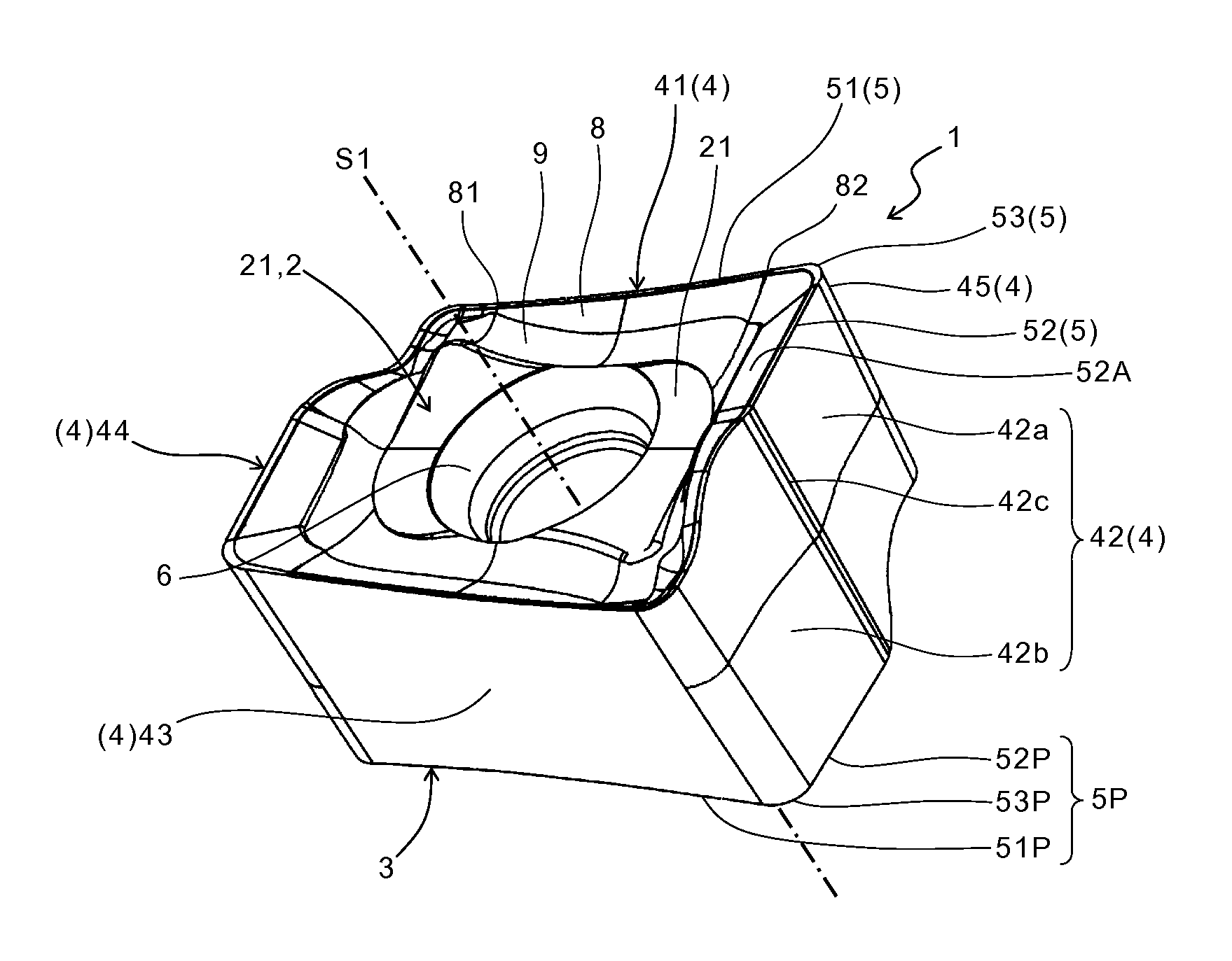
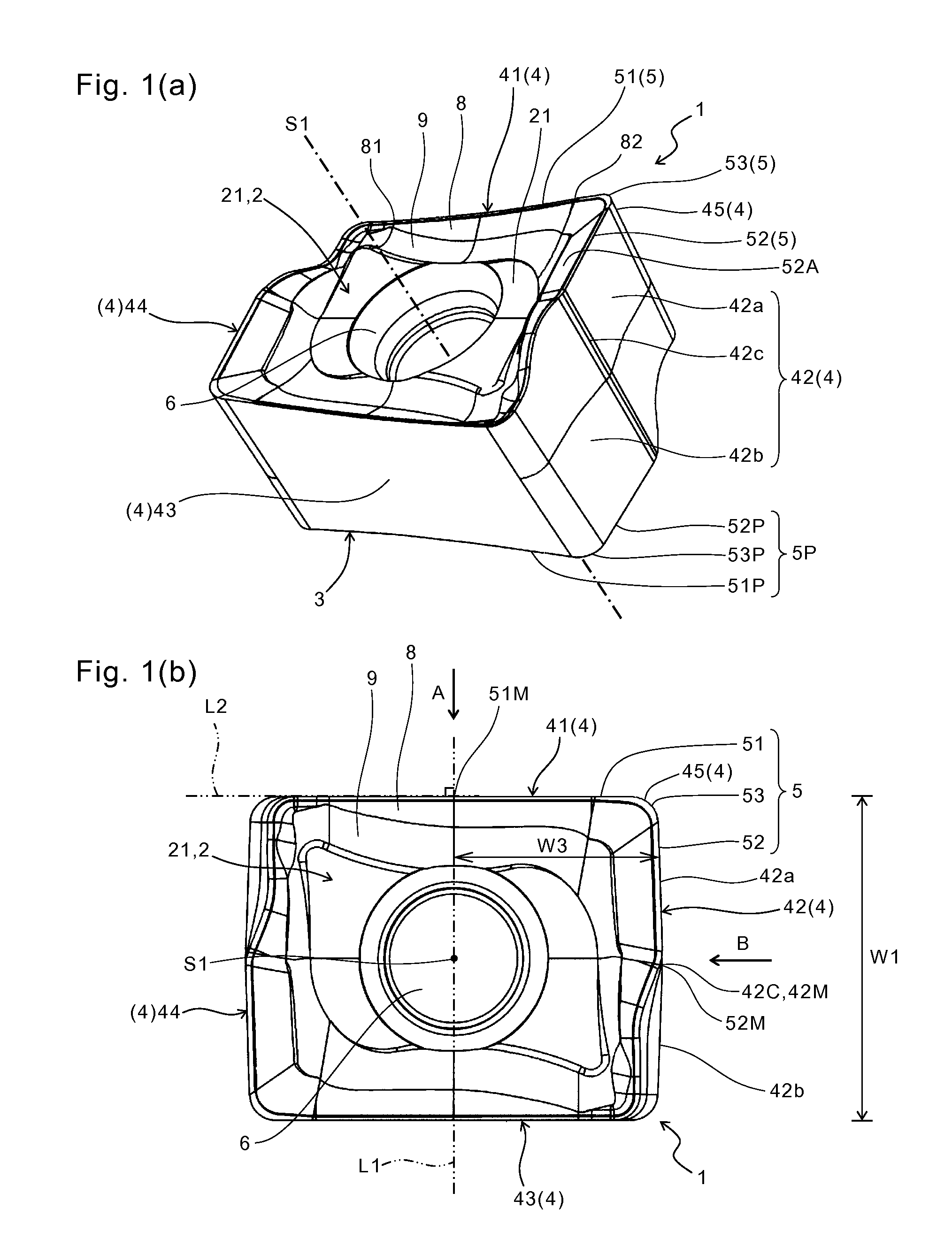
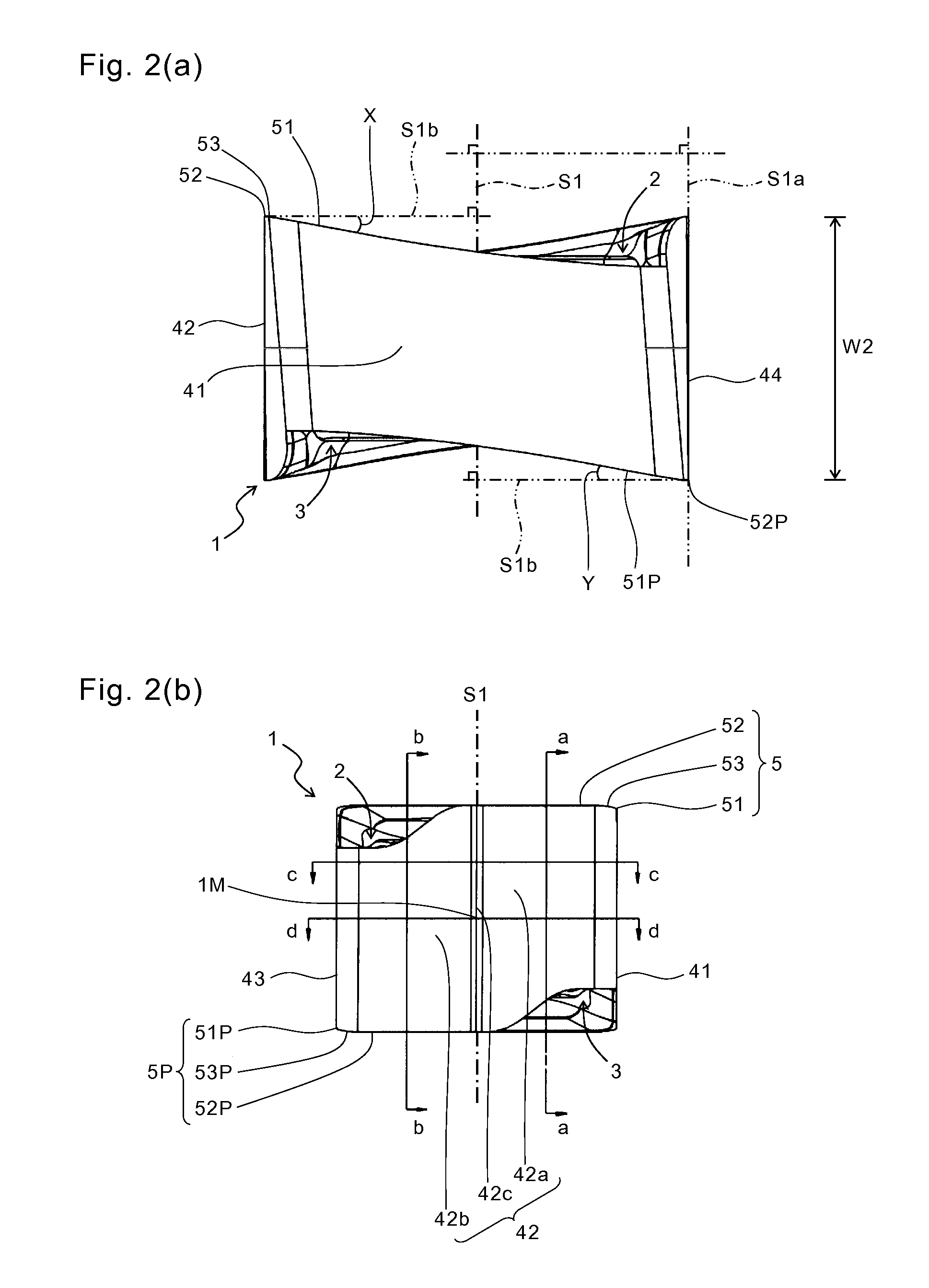
[0016]As shown in FIGS. 1 and 2, the insert 1 of the present embodiment generally includes an upper surface 2, a lower surface 3, a side surface 4 connected to each of the upper surface 2 and the lower surface 3, a through hole 6 extending between the upper surface 2 and the lower surface 3, an upper cutting edge 5 located at an intersection of the upper surface 2 and the side surface 4, and a lower cutting edge 5P located at an intersection of the lower surface 3 and the side surface 4.

[0017]The side surface 4 includes a first side surface 41, a second side surface 42, a third side surface 43 and a fourth side surface 44 which are adjacent to each other in order. As shown in FIG. 1(b), the insert 1 has a rectangular shape (quadrangular shape) whose long side is an outer edge of the i...


PUM

PropertyMeasurementUnit
sizeaaaaaaaaaa
sizeaaaaaaaaaa
thicknessaaaaaaaaaa

Abstract

A cutting insert includes an upper surface; a lower surface; a side surface which is connected to each of the upper surface and the lower surface and includes a first side surface, a second side surface and a third side surface being adjacent to each other in order; an upper cutting edge including an upper major cutting edge located at an intersection of the upper surface and the first side surface, and an upper flat cutting edge located closer to the upper major cutting edge in an intersection of the upper surface and the second side surface; and a lower cutting edge including a lower major cutting edge located at an intersection of the lower surface and the third side surface, and a lower flat cutting edge located closer to the lower major cutting edge in an intersection of the lower surface and the second side surface. The second side surface comprises an upper flank surface connected to the upper flat cutting edge, and a lower flank surface connected to the lower flat cutting edge. As going from the upper surface to the lower surface, the upper flank surface is closer to a central axis extending between the upper surface and the lower surface and the lower flank surface is separated from the central axis in a side sectional view. A cutting tool including the cutting insert, and a method of manufacturing a machined product by using the cutting tool are also provided.

Description

TECHNICAL FIELD[0001]The present invention relates to a cutting insert, a cutting tool, and a method of manufacturing a machined product using them.BACKGROUND ART[0002]As an example of cutting inserts, Japanese Unexamined Patent Publication No. 2004-284010 discloses a reversible cut insert having a rectangular shape in a top view. The cut insert has a structure in which a basal body is twisted around two axial lines.[0003]However, when an attempt is made to ensure a large axial rake angle of a cutting edge in the foregoing cut insert, it is necessary to decrease a forward inclination angle of the cut insert. This makes it difficult to ensure a sufficient clearance angle between a flank surface and a workpiece during a cutting process. Consequently, frictional heat generation occurs due to contact between the flank surface and the workpiece, and there is a risk of early wear of the cut insert.SUMMARY OF THE INVENTION[0004]An object of the present invention is to provide a cutting ins...

Claims


Application Information

Patent Timeline
Patent Type & Authority Applications(United States)
IPC IPC(8): B23C5/20B23C5/10
CPCB23C5/109B23C5/207B23C2200/085Y10T407/23B23C5/205Y10T407/1906Y10T409/303808B23C2200/286Y10T407/1924Y10T407/235B23C5/202B23C2226/315
Inventor ISHI, HIROHISA
Owner KYOCERA CORP
Why Eureka
Try Eureka