Golf club head with flexure

a golf club and head technology, applied in the field of golf club head, can solve the problems of reducing the service life increasing the risk of failure of the golf equipment manufacturer, and increasing the risk of failure of the golf club head

Active Publication Date: 2015-03-24
ACUSHNET CO
View PDF116 Cites 190 Cited by
  • Summary
  • Abstract
  • Description
  • Claims
  • Application Information

AI Technical Summary

Problems solved by technology

Thus, a major challenge is designing the club face and body to resist permanent deformation or failure by material yield or fracture.
However, these environmental effects are beyond the control of the golf equipment manufacturer.
Also, the faces of clubs have been steadily becoming extremely thin.
The thinner faces are more vulnerable to failure.

Method used


Image

  • Golf club head with flexure
  • Golf club head with flexure
  • Golf club head with flexure

Examples


Embodiment Construction

[0074]Other than in the operating examples, or unless otherwise expressly specified, all of the numerical ranges, amounts, values and percentages such as those for amounts of materials, moments of inertias, center of gravity locations, loft and draft angles, and others in the following portion of the specification may be read as if prefaced by the word “about” even though the term “about” may not expressly appear with the value, amount, or range. Accordingly, unless indicated to the contrary, the numerical parameters set forth in the following specification and attached claims are approximations that may vary depending upon the desired properties sought to be obtained by the present invention. At the very least, and not as an attempt to limit the application of the doctrine of equivalents to the scope of the claims, each numerical parameter should at least be construed in light of the number of reported significant digits and by applying ordinary rounding techniques.

[0075]Notwithsta...


PUM


Abstract

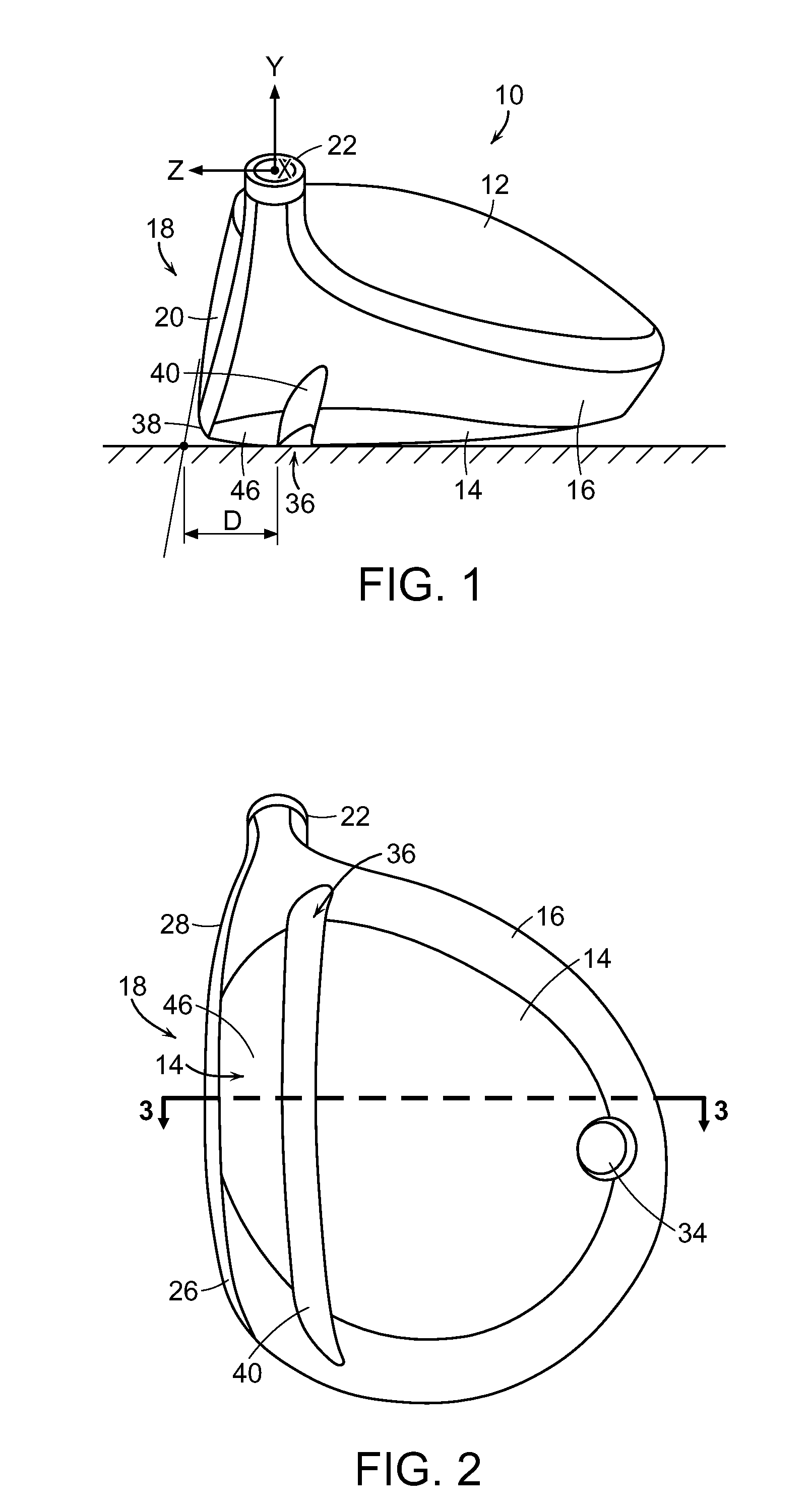
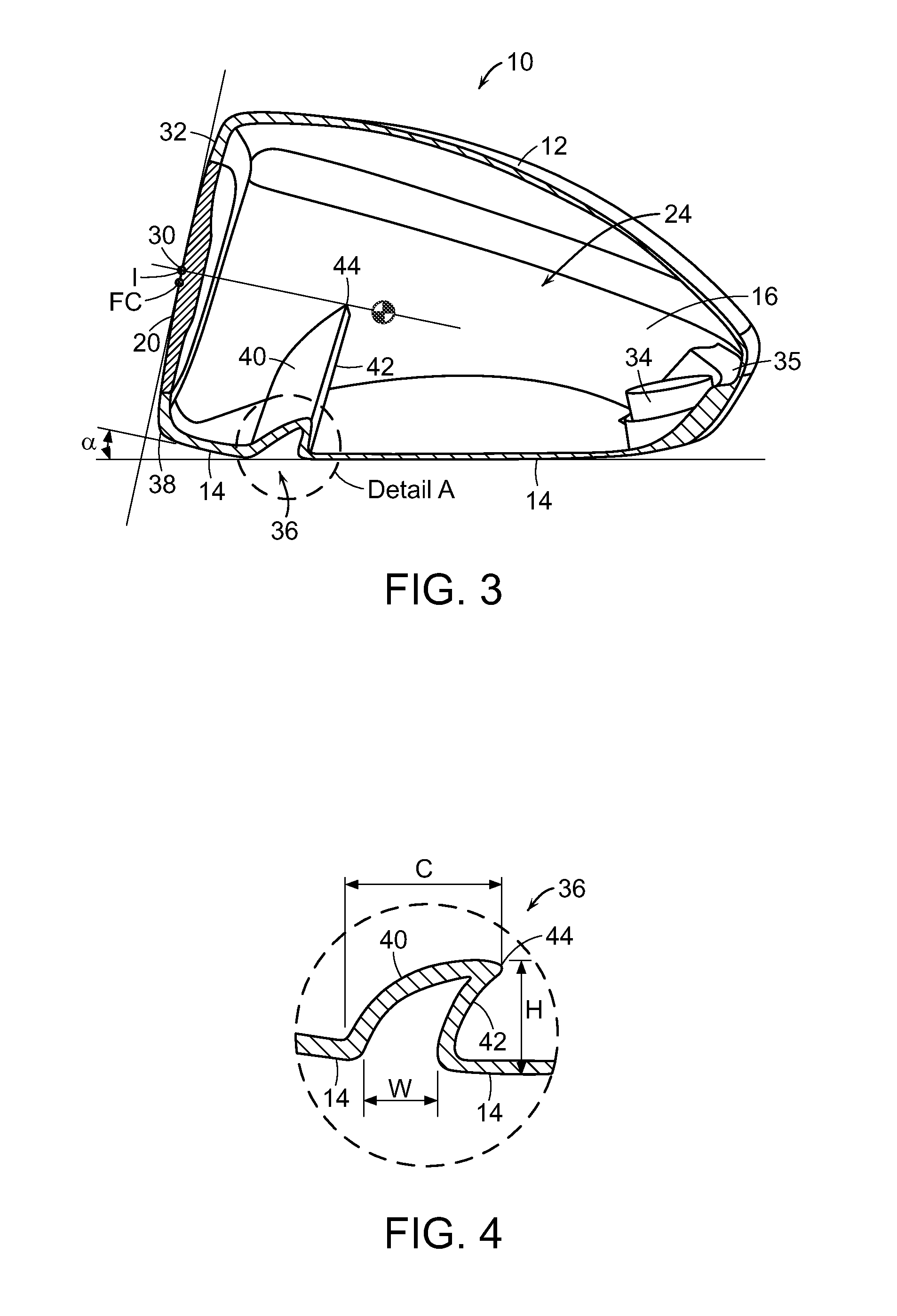
A golf club head including a crown, a sole, a hosel, a face and a flexure. The flexure provides compliance during an impact between the golf club head and a golf ball, and is tuned to vibrate, immediately after impact, at a predetermined frequency.

Description

CROSS-REFERENCE TO RELATED APPLICATIONS[0001]This application is a continuation-in-part of U.S. patent application Ser. No. 13 / 720,885, filed on Dec. 19, 2012, currently pending, which is a continuation-in-part of U.S. patent application Ser. No. 13 / 618,963, filed on Sep. 14, 2012 and currently pending, the disclosures of which are hereby incorporated by reference in their entireties.FIELD OF THE INVENTION[0002]The present invention relates to an improved golf club head. More particularly, the present invention relates to a golf club head having a compliant portion.BACKGROUND[0003]The complexities of golf club design are well known. The specifications for each component of the club (i.e., the club head, shaft, grip, and subcomponents thereof) directly impact the performance of the club. Thus, by varying the design specifications, a golf club can be tailored to have specific performance characteristics.[0004]The design of club heads has long been studied. Among the more prominent con...

Claims


Application Information

Patent Timeline
Patent Type & Authority Patents(United States)
IPC IPC(8): A63B53/04A63B53/06A63B59/00
CPCA63B53/0466A63B59/0092A63B49/06A63B53/06A63B2059/0003A63B2053/0433A63B2053/045A63B2053/0412A63B2053/0491A63B2053/0437A63B2053/042A63B2209/00A63B2209/02A63B60/52A63B60/54A63B53/042A63B53/0412A63B53/045A63B53/0437A63B60/002A63B53/0433A63B53/0458A63B60/02A63B60/00A63B53/0408
Inventor BENNETT, THOMAS ORRINBEZILLA, STEPHANIECLEGHORN, RICHARD L.DESHMUKH, UDAY V.DE LA CRUZ, NOAHGALVAN, DARRYL C.GOLDEN, CHARLES E.INES, MARNIMORIN, JOHNMURPHY, STEPHEN S.MYRHUM, MARK C.ZIMMERMAN, GERY
Owner ACUSHNET CO
Why Eureka
Try Eureka