
Surgical staple-clip and applier

a stapler and applier technology, applied in the field of medical devices, can solve the problems of clip movement or slippage, necrosis of tissue, and heavy bulky staplers used for staple application, and achieve the effect of maintaining nourishment to body tissue and constricting or occlusing

Inactive Publication Date: 2015-04-07
APPL MEDICAL RESOURCES CORP
View PDF27 Cites 114 Cited by
  • Summary
  • Abstract
  • Description
  • Claims
  • Application Information

AI Technical Summary

Benefits of technology

The staple-clip provides effective traction and secure positioning with minimal compressive force, preventing tissue slippage and necrosis while maintaining tissue nourishment, suitable for various surgical procedures including laparoscopic and hand-assisted surgeries.

Problems solved by technology

It is not uncommon for laparoscopic surgeons to discover that even the largest clip available is undersized for a particular surgical procedure Moreover, clips will occasionally move about or slip off the tissue to which they have been applied.
This excessive compression may cause necrosis of tissue since nutrition to the tissue is interrupted or eliminated.
Surgical staples have proved to be effective, however, the staplers used for applying the staples are often bulky and require a very strong closing or compressing force, which is not ideal for minimally invasive or laparoscopic surgeries.

Method used


Image

  • Surgical staple-clip and applier
  • Surgical staple-clip and applier
  • Surgical staple-clip and applier

Examples


Embodiment Construction

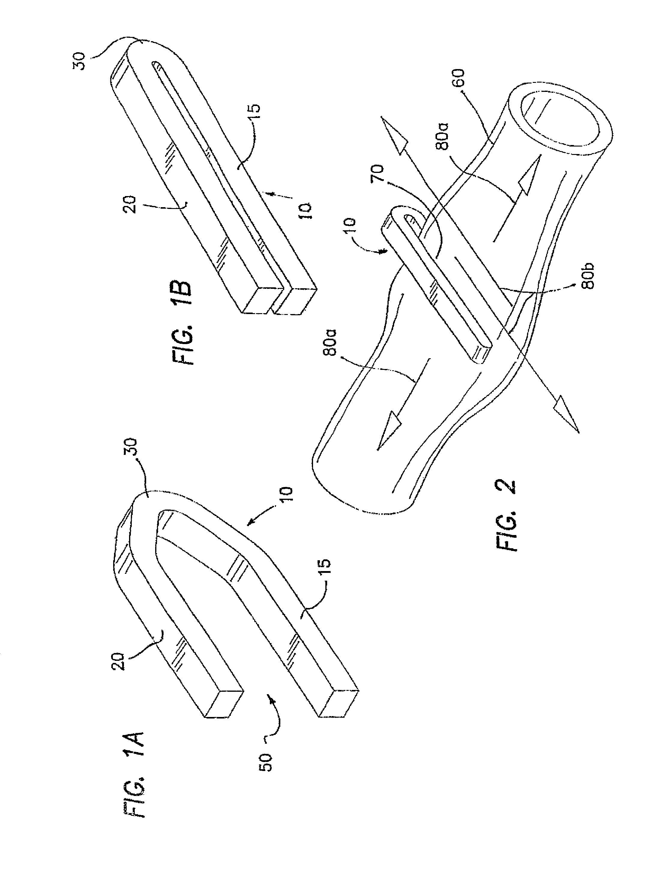
[0043]FIGS. 1 and 2 illustrate a surgical clip 10 of the prior art having a generally open shape including a first leg 15, a second leg 20 and a base 30 connecting the first leg 15 and the second leg 20. The clip 10 can be positioned around a body conduit or passage, e.g., a blood vessel, and compressed using a clip applier 150 as illustrated in FIG. 5(a). The clip applier 150 generally comprises an elongate shaft 155, sized and configured to fit through a surgical trocar port, a distal end 160 having a pair of opposed jaws 165, 167 and a proximal end 170 having a handle 180 to open and close the jaws 165, 167 The clip 10, held in an open condition, is supplied to the jaws 165, 167 either automatically or manually The clip 10 is advanced to a desired site and subsequently closed or compressed. With the first and second legs 15 and 20 properly formed, the jaws 165, 167 can be opened and moved away from the tissue leaving the clip 10 clamped around the tissue. The clip 10 derives its ...


PUM


Abstract

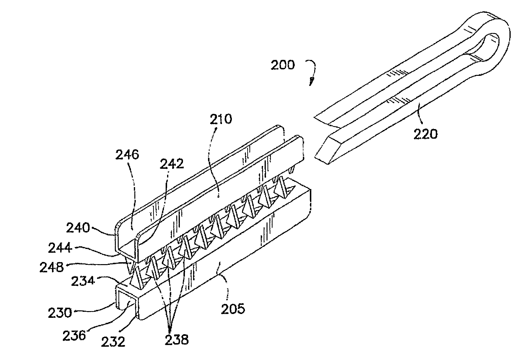
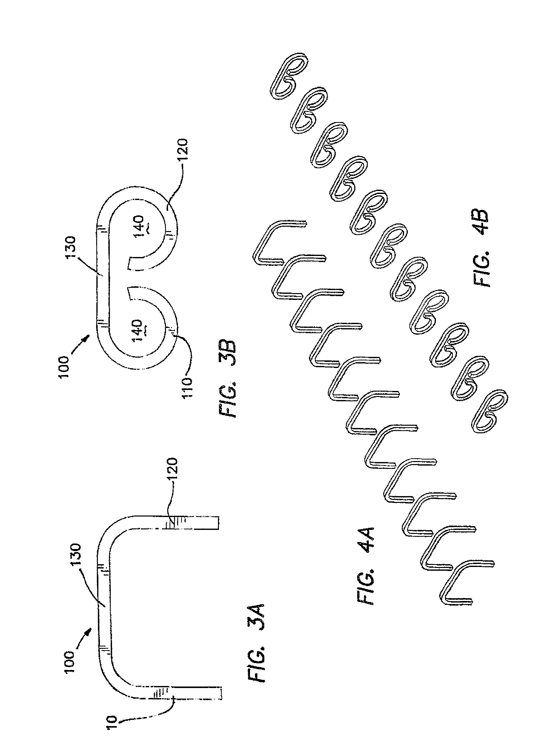
A surgical staple-clip including a clip component and a securing member is used in a wide range of surgical procedures. The staple-clip may be introduced to a surgical site in an un-assembled condition through a small port or trocar. An applier for the staple-clip comprising a pair of opposed jaw-like channels is provided to position and apply the clip component and the securing member. The clip component is positioned around a target tissue and is compressed or clamped upon the tissue using only the force required for a specific surgical procedure such as occlusion, ligation or fixation. When the clip component is properly applied, the securing member is urged forward and over the clip component to secure the staple-clip. The clip component may include traction enhancement features such as surface interruptions, bumps, valleys and ridges. With the staple-clip of the invention, the force required to constrict or occlude the tissue is separate from the force required to secure and maintain the staple-clip in position and, as a result, the body tissue is not over-compressed and nourishment to the body tissue is maintained. Other aspects of the invention include thumb actuated clip appliers for use in hand assisted laparoscopy (HAL) In one embodiment, a clip applier includes a handle and a thumb actuated mechanism that is used to slidably release clips onto a body tissue or vessel by sliding the thumb actuated mechanism forward and backward using only one hand. In another aspect of the invention, a two-stage clip is disclosed having a clip component and a staple component for securing the clip after it has been properly positioned.

Description

CROSS-REFERENCE TO RELATED APPLICATIONS[0001]This application is a divisional of U.S. patent application Ser. No. 10 / 533,398, filed on Apr. 30, 2005, currently pending, which is a 371 international application of PCT Application No. PCT / US03 / 040318, filed on Dec. 16, 2003, which claims benefit of U.S. Provisional Patent Application No. 60 / 434,344, filed on Dec. 17, 2002, the disclosures of which are hereby incorporated by reference as if set forth in full herein.BACKGROUND OF THE INVENTION[0002]1. Field of the Invention[0003]This invention generally relates to medical devices and, more specifically, to a staple-clip and applier adapted for use in surgical procedures[0004]2. Discussion of the Prior Art[0005]Clips and staples are widely used in many surgical procedures such as occlusion, ligation and fixation of various body tissues and vessels. Clips are generally U-shaped, open-ended wires that are positioned around a target tissue and clamped together to constrict or occlude the ti...

Claims


Application Information

Patent Timeline
Patent Type & Authority Patents(United States)
IPC IPC(8): A61B17/08A61B17/00A61B17/064A61B17/068A61B17/122A61B17/128
CPCA61B17/0643A61B17/0644A61B17/0682A61B17/122A61B17/08A61B17/105A61B17/068A61B17/1285A61B2017/00858A61B2017/0641A61B2017/0649A61B2017/1225
Inventor HART, CHARLES C
Owner APPL MEDICAL RESOURCES CORP
Learn More