Method of manufacturing flange structure

a manufacturing method and flange technology, applied in the direction of metal-working feeding devices, handling devices, forging/pressing/hammering apparatuses, etc., can solve the problems of high cost, low manufacturing rate, and hot forging

Inactive Publication Date: 2015-04-14
MATEC CO LTD
View PDF11 Cites 1 Cited by
  • Summary
  • Abstract
  • Description
  • Claims
  • Application Information

AI Technical Summary

Benefits of technology

[0011]In view of the background circumstances described above, the present invention provides a method through which a dual-shaft flange structure with a shaft portion at both sides of a flange that extends outward is efficiently manufacturable.

Problems solved by technology

However, hot forging is disadvantageous, in that: the cost is increased (as hot forging requires a large-sized device); a manufacturing rate is low; skill and experience are required; additional processes such as cutting and grinding are required after forging for components requiring high dimension precision (as hot forging hardly results in final products with good surfaces); and the like.
However, such method is not practically applicable to a manufacturing of, for instance, a component that requires a greatly-overhanging flange because the pressure at the time of forming the component is excessively increased.
Thus, even when an attempt is made to squeeze the head H and to form the shaft portion 3 at the same time, most of the material may flow outward, and thus the shaft portion 3 will be difficult to be formed.

Method used


Image

  • Method of manufacturing flange structure
  • Method of manufacturing flange structure
  • Method of manufacturing flange structure

Examples


Embodiment Construction

[0039]An exemplary embodiment according to the aspect of the invention will be described with reference to FIGS. 1 to 23.

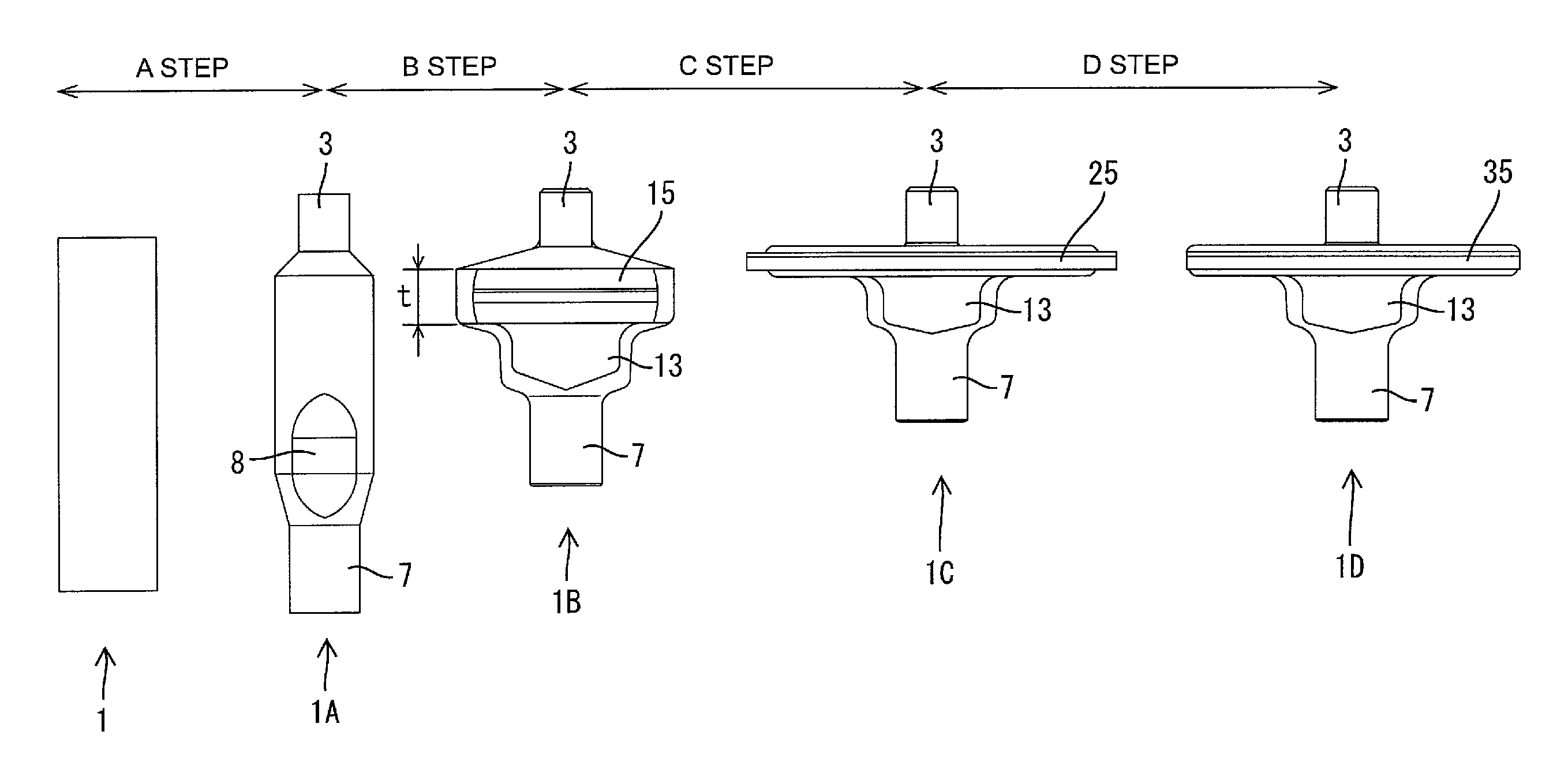
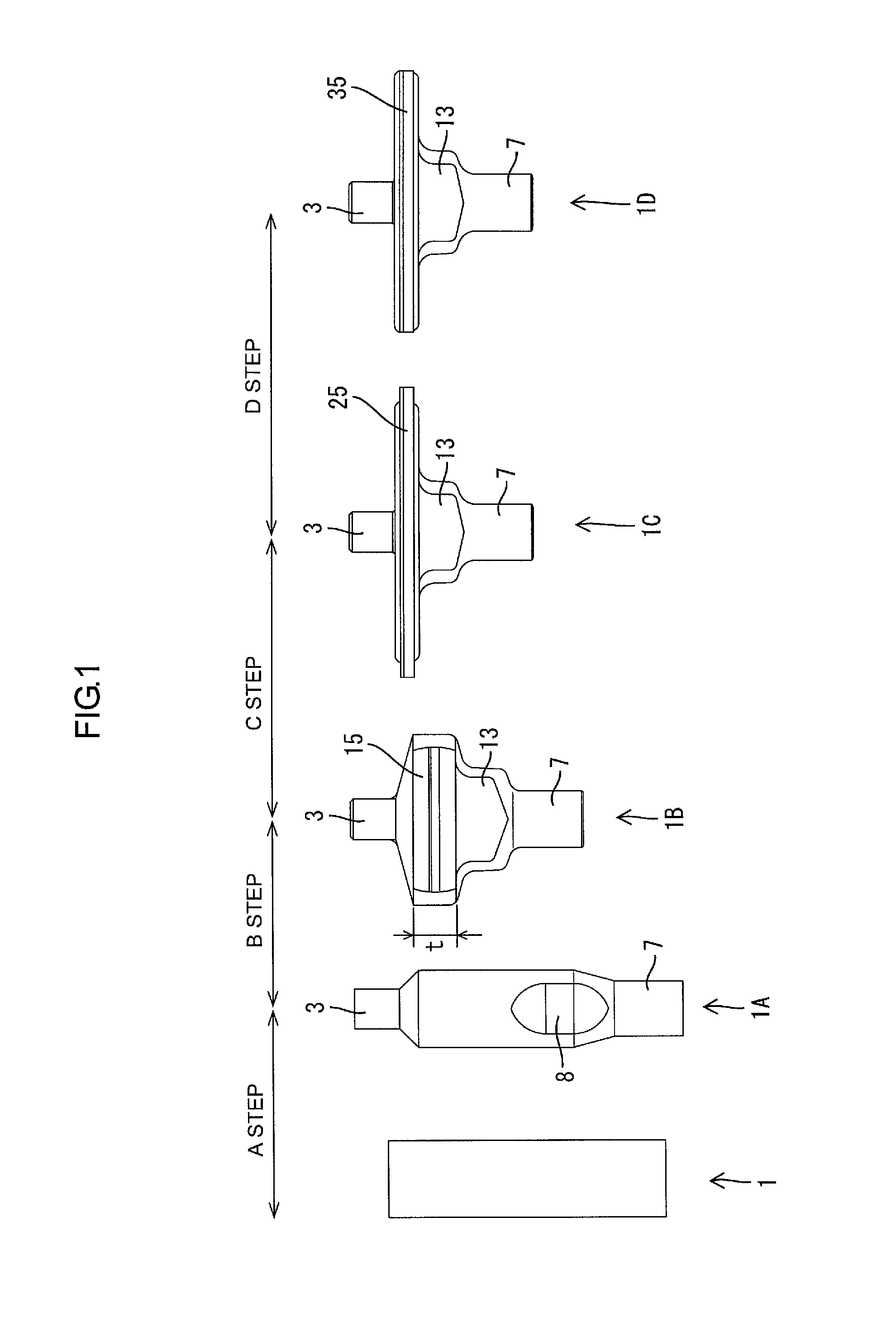
[0040]A flange structure to be manufactured according to this exemplary embodiment is an anchoring block 1D for use as a parking brake for vehicles (hereinafter referred to as “anchoring block 1D”). The anchoring block 1D includes a substantially elliptic flange 35 extending outward in the radial direction with shafts 3 and 7 respectively positioned at both sides of the flange 35. In this exemplary embodiment, a cylindrical material 1 illustrated in FIG. 1 is formed into the anchor block 1D through four steps A to D described as follows. The material 1 is exemplarily made of alloyed steel.

[0041](1) In the Step A, the material 1 is formed into a primary product 1A with the shafts 3 and 7 at respective ends by cold or warm forging.

[0042](2) In the Step B, the primary product 1A is formed into a secondary product 1B having a first overhang 15 thicker than the flange ...


PUM


Abstract

A method of manufacturing a flange structure includes: forming a primary product by extending a columnar material in an axial direction by cold or warm forging such that first shaft portion and a second shaft portion are formed at a first axial end of the material and a second axial end of the material, respectively; forming a secondary product by making a middle portion of the primary product overhang outwardly by cold or warm forging such that a first overhang having a thickness greater than that of the flange is formed; forming a tertiary product by squeezing the first overhang by cold or warm forging such that a second overhang having an outline greater than that of the flange is formed; and defining an outer edge of the flange by cutting off an excessive portion of the second overhang. The second overhang without the excessive portion is the flange.

Description

BACKGROUND[0001]1. Technical Field[0002]The present invention relates to a method of manufacturing a flange structure.[0003]2. Description Of Related Art[0004]Block anchors for use in parking brakes for vehicles, for instance, have flanges that greatly and elliptically overhang outward from outer circumferences of shafts. In manufacturing such component, the flange is often formed by hot forging because material is greatly deformed.[0005]However, hot forging is disadvantageous, in that: the cost is increased (as hot forging requires a large-sized device); a manufacturing rate is low; skill and experience are required; additional processes such as cutting and grinding are required after forging for components requiring high dimension precision (as hot forging hardly results in final products with good surfaces); and the like.[0006]Use of cold forging has been examined in all processes. However, such method is not practically applicable to a manufacturing of, for instance, a component...

Claims


Application Information

Patent Timeline
Patent Type & Authority Patents(United States)
IPC IPC(8): B21D43/28B21K23/04
CPCB21K23/04
Inventor MASUYAMA, TAKEHIKO
Owner MATEC CO LTD
Why Eureka
Try Eureka