Bending apparatus for rod-shaped workpieces

a technology of bending apparatus and workpiece, which is applied in the field of bending apparatus for rod-shaped workpieces, can solve the problems of not being able to convey the workpiece backwards, and the workpiece is not even possible to be straigh

Inactive Publication Date: 2015-06-30
WAFIOS AKTIENGES
View PDF38 Cites 6 Cited by
  • Summary
  • Abstract
  • Description
  • Claims
  • Application Information

AI Technical Summary

Benefits of technology

[0007]As a result of the problems in the prior art, an object of the present invention is to provide a bending device such that it is also possible to cut off the workpiece quite close to its last bend with no, or only an extremely short, straight end piece, without the need for a movement of the workpiece.

Problems solved by technology

Although the cutting plane of the cutting device can thus be moved up fairly close to the bending head, in different cases of application this still leads to a straight end piece which turns out to be longer than desired.
However, the required reversal of the conveyance direction of the workpiece leads to an undesired reduction in the machine's throughput.
In addition, some bending devices also have no movable feeder, in which case it is not even possible to convey the workpiece backwards.
Moreover, a rearward conveyance of the workpiece via the feeder is also very problematic when large workpiece diameters are used.

Method used


Image

  • Bending apparatus for rod-shaped workpieces
  • Bending apparatus for rod-shaped workpieces
  • Bending apparatus for rod-shaped workpieces

Examples


Embodiment Construction

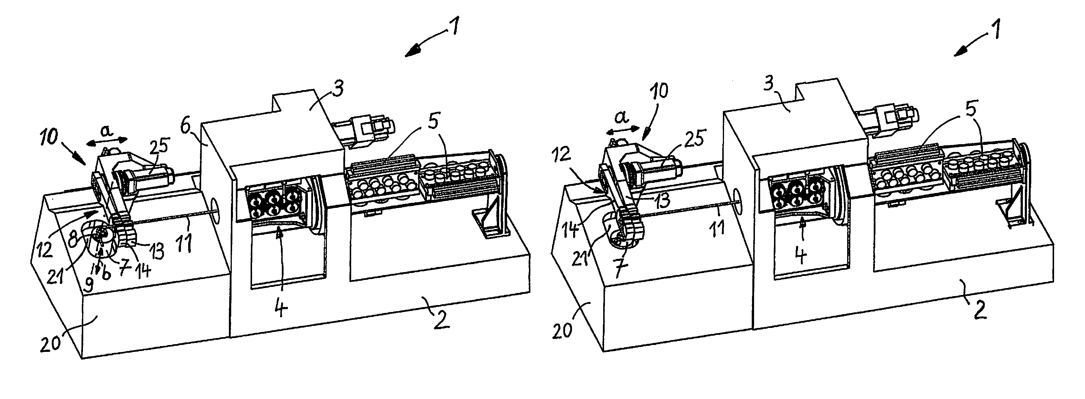
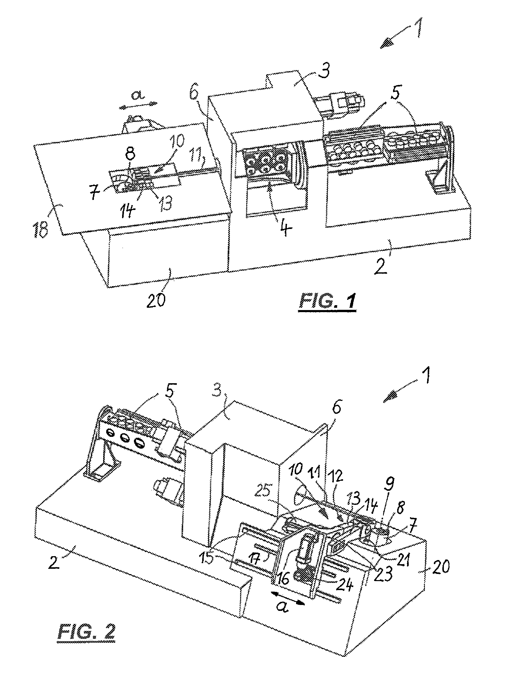
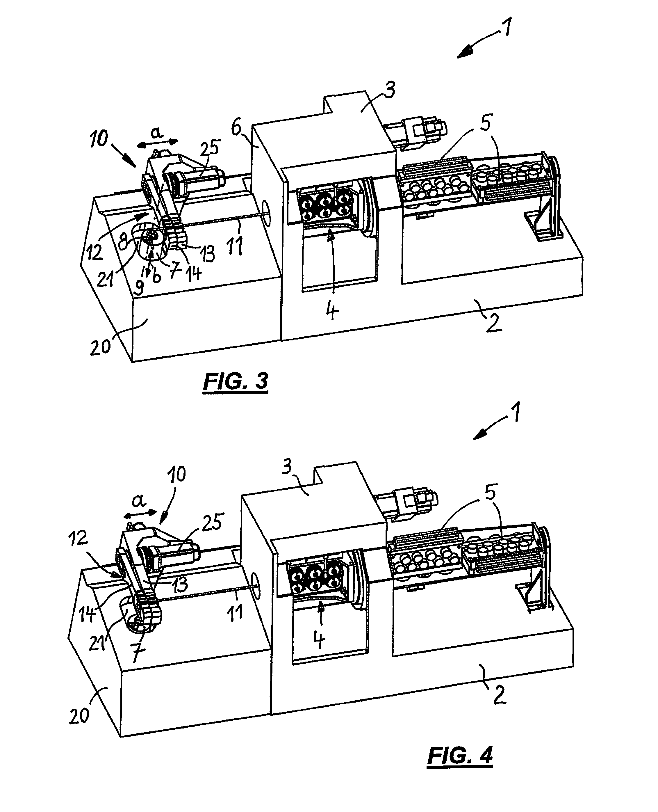
[0045]FIGS. 1 to 4 show a diagrammatic perspective representation of a bending device 1, wherein in the view in FIGS. 1, 3 and 4 the chosen viewing direction is at an angle from above from front to back, and in the view in FIG. 2 the chosen viewing direction is at an angle from above from back to front.

[0046]The bending machine 1 comprises a machine frame 2 and a housing 3 mounted thereon, in which a feed device 4 in the form of a roller feed with three pairs of series-connected rollers is rotatably mounted.

[0047]Two straightening devices 5 offset by 90° to each other are situated at the back of the housing 3, are connected to the rotatable feed device 4, and can be twisted with the latter about the central axis of a workpiece 11 in the form of a wire.

[0048]Arranged in front of the end face 6 of the housing 3 are a bending head 7, bearing a mandrel 8 at the top, which is rotatable about a rotation axis 9 (FIGS. 2 and 3), as well as a cutting device 10 which can be moved along a trav...


PUM

PropertyMeasurementUnit
widthaaaaaaaaaa
areaaaaaaaaaaa
rotation axisaaaaaaaaaa

Abstract

A bending device for rod-shaped workpieces having a bending head with a mandrel rotatable about a rotation axis, a cutting device for cutting the respective workpiece in a cutting plane, and a feed and straightening device for feeding the workpieces to the bending head, the cutting device capable of being moved along a travel path in the feed direction of the workpieces, with the bending head capable of being shifted between an operating position in which it is moved towards the workpiece and an inactive end position remote therefrom, the bending head, in order to assume its operating position, can be moved into the travel path of the cutting device, whereas, when assuming its inactive end position, it is positioned outside the travel path of the cutting device, and, when the bending head is situated in its inactive end position, the cutting device can be moved downstream on its travel path at least partly over the area of the operating position of the bending head.

Description

[0001]The present application claims priority to German Patent Application No. 10 2011 106 942.2 filed on Jul. 8, 2011, which said application is incorporated by reference in its entirety herein.FIELD OF THE INVENTION[0002]The present invention relates to a bending apparatus for rod-shaped workpieces.BACKGROUND OF THE INVENTION[0003]With bending devices it is frequently desired that there be only a short, straight end piece between the cutting plane and the last bend which the bending head produces.[0004]A bending device is known from EP 0 379 030 B1 (corresponding to DE 690 03 116 T2) in which upstream of the bending head, a cutting device is provided that can be moved in feed direction of the workpiece. It is thus possible to vary the distance between the end of the workpiece produced after cutting and the bending head. However, with this known bending machine, the cutting device, even in its position moved furthest towards the bending head, is still a clear distance from the bend...

Claims


Application Information

Patent Timeline
Patent Type & Authority Patents(United States)
IPC IPC(8): B21F1/00
CPCB21F1/00B21F1/006
Inventor FRIES, STEFANMOECK, JOERGWEIBLEN, FRANKSCHWEIKARDT, HARRY
Owner WAFIOS AKTIENGES
Why Eureka
Try Eureka