Fan motor apparatus having diffuser unit for vacuum cleaner

a technology of fan motor and dimmer unit, which is applied in the direction of positive displacement liquid engine, piston pump, liquid fuel engine, etc., can solve the problems of noise generated by the operation of the fan motor apparatus, problems may arise, and complex structur

Active Publication Date: 2015-07-28
SAMSUNG ELECTRONICS CO LTD
View PDF12 Cites 67 Cited by
  • Summary
  • Abstract
  • Description
  • Claims
  • Application Information

AI Technical Summary

Problems solved by technology

However, as the vacuum cleaner is operated, noise is generated due to operation of the fan motor apparatus and air current discharging out of the fan motor apparatus.
Furthermore, an air stream, which is discharged out of the fan motor apparatus, can include minute matters which are left even after the dust removal operation of the vacuum cleaner.
Problems may arise if such minute dusts or carbon dusts are not completely removed by the discharge filter, and carried along the discharged air stream.
Accordingly, structure becomes complicated, the number of parts required to form airflow passages is increased, and the overall volume is increased.
However, similar to the drawback with conventional art 1, conventional arts 2 and 3 also need separate passages to draw in and discharge out an air flow with respect to the fan motor unit.
Accordingly, air passages may become complicated, the number of necessary parts is increased, and the overall size is increased.
Furthermore, according to conventional arts 2 and 3, since it may be necessary to form a passage to draw in airflow in a lower portion of the fan motor unit, the fan motor unit has to be installed at a relatively higher position, causing a vacuum cleaner to have a higher center of mass and subsequently a decreased stability.

Method used


Image

  • Fan motor apparatus having diffuser unit for vacuum cleaner
  • Fan motor apparatus having diffuser unit for vacuum cleaner
  • Fan motor apparatus having diffuser unit for vacuum cleaner

Examples


Embodiment Construction

[0036]The following detailed description is provided to assist the reader in gaining a comprehensive understanding of the methods, apparatuses, and / or systems described herein. Accordingly, various changes, modifications, and equivalents of the systems, apparatuses and / or methods described herein will be suggested to those of ordinary skill in the art. Also, descriptions of the well-known functions and constructions may be omitted for increased clarity and conciseness.

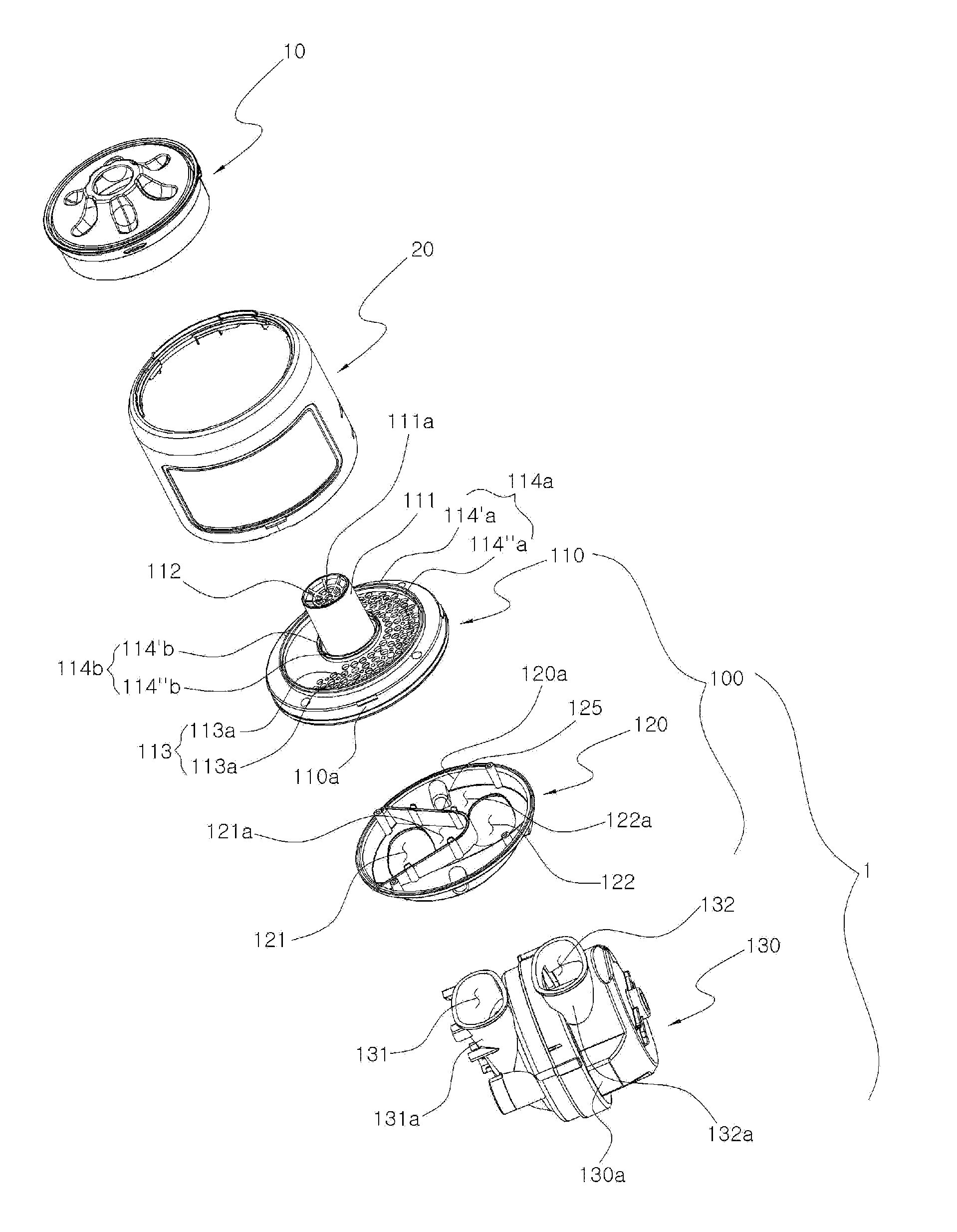
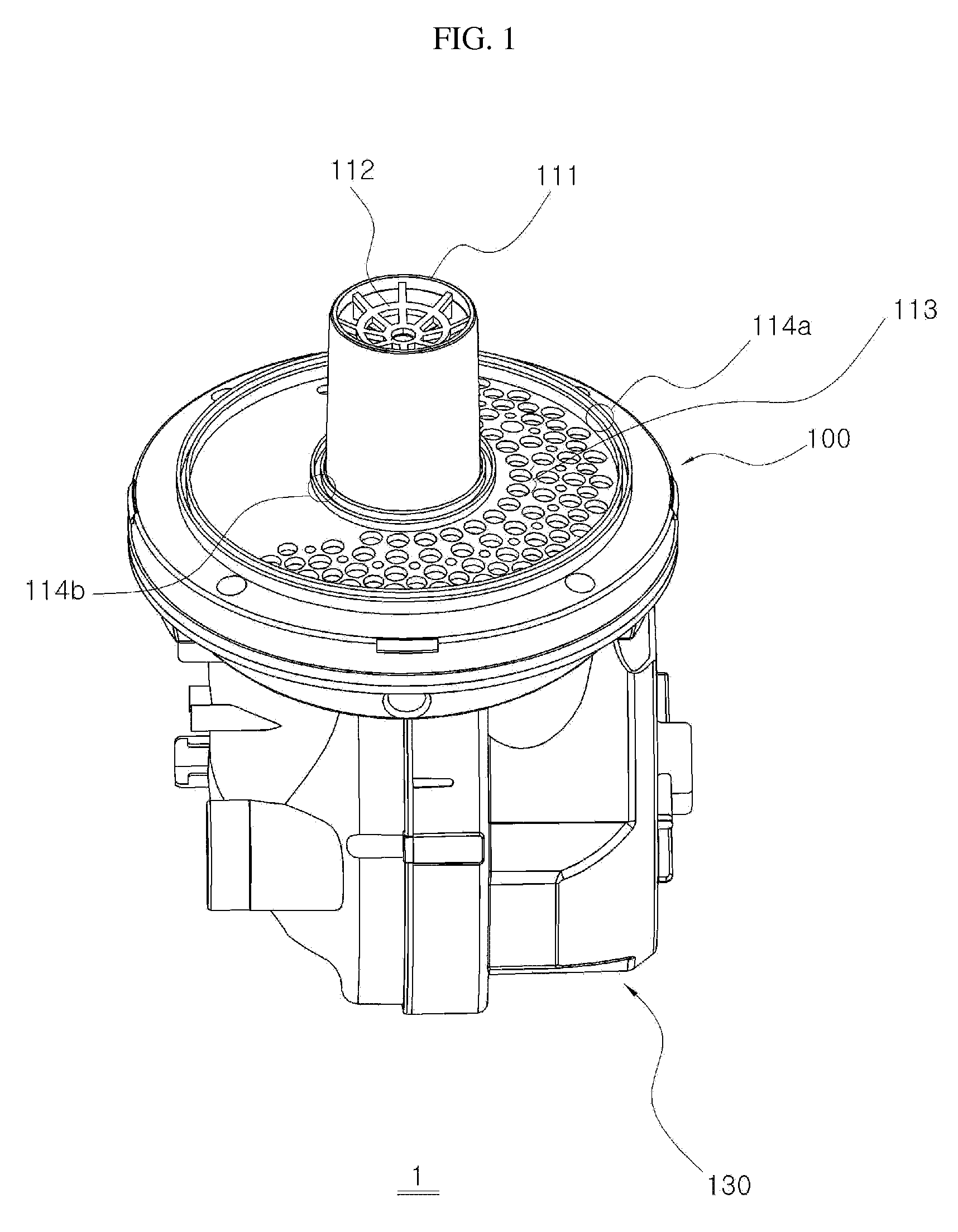
[0037]Referring to the accompanying drawings, the fan motor apparatus 1 may include a diffuser unit 100 and a fan motor unit 130.

[0038]The fan motor unit 130 may be installed within the vacuum cleaner 2 (FIG. 4) and form an air passage to draw in an air stream and an air passage to discharge an air stream. The fan motor unit 130 may include a motor 150 to which an impeller unit 140 may be connected (FIG. 4), and a fan motor casing 130a. Specifically, FIG. 4 illustrates an exemplary casing of the motor 150.

[0039]The fan...


PUM


Abstract

A fan motor apparatus of a vacuum cleaner having a diffuser unit is provided. The fan motor apparatus of a vacuum cleaner includes a fan motor unit into and from which an air stream is introduced and discharged in the same direction, and a diffuser unit having an air suction area to discharge an air stream to the fan motor unit through a fluid passage surface, the fluid passage surface through which an air stream is drawn in and discharged out of the diffuser. An air discharge area of the diffuser unit may receive the air stream discharged from the fan motor unit, and distribute and discharge the air stream through a perimeter of the air suction area of the fluid passage surface.

Description

CROSS-REFERENCE TO RELATED APPLICATIONS[0001]This application claims the benefit under 35 U.S.C. §119(e) of U.S. Provisional Application No. 61 / 152,762, filed on Feb. 16, 2009, in the United States Patent and Trademark Office, and under 35 U.S.C. §119(a) of a Korean Patent Application No. 10-2009-0037697, filed on Apr. 29, 2009, in the Korean Intellectual Property Office, the disclosures of which are incorporated herein by reference for all purposes.BACKGROUND[0002]1. Field[0003]The following description relates to a vacuum cleaner, and more particularly, to a fan motor apparatus for use in an industrial, domestic, or commercial vacuum cleaner, which has a diffuser unit formed therein.[0004]2. Description of the Related Art[0005]A vacuum cleaner generally may have a fan motor apparatus to forcefully draw in external air stream. As the fan motor apparatus starts operating, the vacuum cleaner starts cleaning operation by drawing in external air including foreign matters of the target ...

Claims


Application Information

Patent Timeline
Patent Type & Authority Patents(United States)
IPC IPC(8): F04D29/70A47L9/10F04D29/40F04D29/44A47L5/22A47L9/22A47L5/12A47L9/12A47L9/00
CPCA47L5/12A47L5/22A47L9/0081A47L9/102A47L9/122A47L9/22F04D29/40F04D29/44F04D29/441F04D29/70
Inventor YOO, DONG-HUN
Owner SAMSUNG ELECTRONICS CO LTD
Why Eureka
Try Eureka